Chapter 2---System Description
•LED indication
•IIC serial bus interface
Y/G
Pb/B
Pr/R
IIC_CLK
IIC_DATA
+5.1V_STBY
+5.1V
+15V
| B2 | RED | |||
| B4 | GRN |
|
| |
| B6 | BLU | |||
B13 |
|
|
| ||
|
|
|
| ||
A13 | B8 | HOR |
| ||
| |||||
A16 | /SELECT | ||||
| |||||
B16 | B12 | ||||
|
|
| |||
B15 |
|
|
|
| |
B14 |
|
|
|
| |
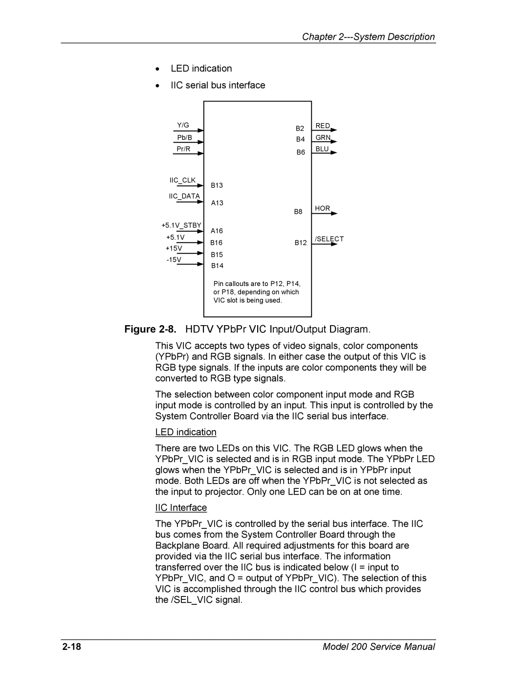
Pin callouts are to P12, P14, or P18, depending on which VIC slot is being used.
Figure 2-8. HDTV YPbPr VIC Input/Output Diagram.
This VIC accepts two types of video signals, color components (YPbPr) and RGB signals. In either case the output of this VIC is RGB type signals. If the inputs are color components they will be converted to RGB type signals.
The selection between color component input mode and RGB input mode is controlled by an input. This input is controlled by the System Controller Board via the IIC serial bus interface.
LED indication
There are two LEDs on this VIC. The RGB LED glows when the YPbPr_VIC is selected and is in RGB input mode. The YPbPr LED glows when the YPbPr_VIC is selected and is in YPbPr input mode. Both LEDs are off when the YPbPr_VIC is not selected as the input to projector. Only one LED can be on at one time.
IIC Interface
The YPbPr_VIC is controlled by the serial bus interface. The IIC bus comes from the System Controller Board through the Backplane Board. All required adjustments for this board are provided via the IIC serial bus interface. The information transferred over the IIC bus is indicated below (I = input to YPbPr_VIC, and O = output of YPbPr_VIC). The selection of this VIC is accomplished through the IIC control bus which provides the /SEL_VIC signal.
Model 200 Service Manual |