|
|
| Chapter |
|
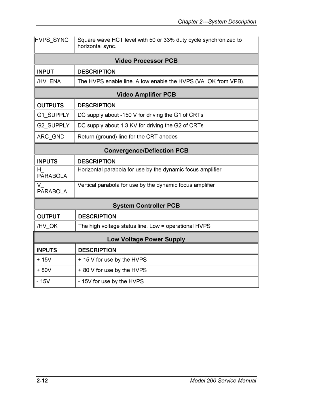
| HVPS_SYNC |
| Square wave HCT level with 50 or 33% duty cycle synchronized to |
|
|
|
| ||
|
|
| horizontal sync. |
|
|
|
|
|
|
|
|
|
|
|
|
|
| Video Processor PCB |
|
|
|
|
|
|
| INPUT |
| DESCRIPTION |
|
|
|
|
|
|
| /HV_ENA |
| The HVPS enable line. A low enable the HVPS (VA_OK from VPB). |
|
|
|
|
|
|
|
|
|
|
|
|
|
| Video Amplifier PCB |
|
|
|
|
|
|
| OUTPUTS |
| DESCRIPTION |
|
|
|
|
|
|
| G1_SUPPLY |
| DC supply about |
|
|
|
|
|
|
| G2_SUPPLY |
| DC supply about 1.3 KV for driving the G2 of CRTs |
|
|
|
|
|
|
| ARC_GND |
| Return (ground) line for the CRT anodes |
|
|
|
|
|
|
|
|
|
|
|
|
|
| Convergence/Deflection PCB |
|
|
|
|
|
|
| INPUTS |
| DESCRIPTION |
|
|
|
|
|
|
| H_ |
| Horizontal parabola for use by the dynamic focus amplifier |
|
| PARABOLA |
|
|
|
|
|
|
|
|
| V_ |
| Vertical parabola for use by the dynamic focus amplifier |
|
| PARABOLA |
|
|
|
|
|
|
|
|
|
|
|
|
|
|
|
| System Controller PCB |
|
|
|
|
|
|
| OUTPUT |
| DESCRIPTION |
|
|
|
|
|
|
| /HV_OK |
| The high voltage status line. Low = operational HVPS |
|
|
|
|
|
|
Low Voltage Power Supply
INPUTS
DESCRIPTION
| + 15V | + 15 V for use by the HVPS |
|
|
|
|
|
| + 80V | + 80 V for use by the HVPS |
|
|
|
|
|
| - 15V | - 15V for use by the HVPS |
|
|
|
|
|
Model 200 Service Manual |