Chapter 4---Maintenance (Removal/Replacement)
and carefully cut the socket connectors away from the Video Amplifier PCB. The spacers between the CRT Socket Connectors can be discarded.
4.13 Scan Reversal PCB
The Scan Reversal PCB is located on the right side of the Electronic Module.
To remove the Scan Reversal PCB:
1. Remove the projector rear cover.
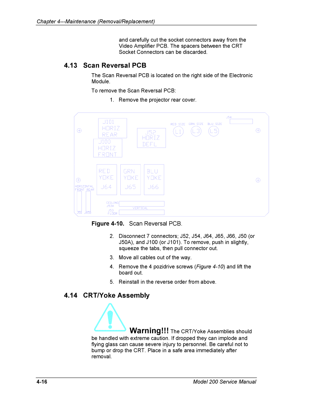
Figure 4-10. Scan Reversal PCB.
2.Disconnect 7 connectors; J52, J54, J64, J65, J66, J50 (or J50A), and J100 (or J101). To remove, push in slightly, squeeze the tabs, then pull connector out.
3.Move all cables out of the way.
4.Remove the 4 pozidrive screws (Figure
5.Reinstall in the reverse order from above.
4.14CRT/Yoke Assembly
 Warning!!! The CRT/Yoke Assemblies should be handled with extreme caution. If dropped they can implode and flying glass can cause severe injury to personnel. Be careful not to bump or drop the CRT. Place in a safe area immediately after removal.
Model 200 Service Manual |