|
|
|
| Chapter |
|
|
|
|
|
|
|
| I | 9 | Left blanking | Data for adjustment of left blanking |
|
| I | 12 | Top blanking | Data for adjustment of top blanking |
|
| I | 12 | Bottom blanking | Data for adjustment of bottom blanking |
|
| I | 8 | Horz. phase | Data for adjustment of horizontal phase |
|
| I | 12 | Vert. phase | Data for adjustment of vertical phase |
|
| O | 3 | Frequency bands | The frequency band associated with the current |
|
|
|
|
| signal |
|
| O | 1 | /RTG_OK | A low on this line indicates an operational RTG |
|
|
|
|
| board |
|
| O | 2 | RTG_MODEL | The revision of the RTG board |
|
| O | 12 | H_COUNT | The number of horizontal lines associated with |
|
|
|
|
| the current signal |
|
| O | 12 | V_COUNT | Data for V_COUNT |
|
| O | 3 | INPUT_MODE | Data indicating the selected sync signals |
|
| O | 1 | INTERLACE | High indicates interlace pattern |
|
|
|
|
|
|
|
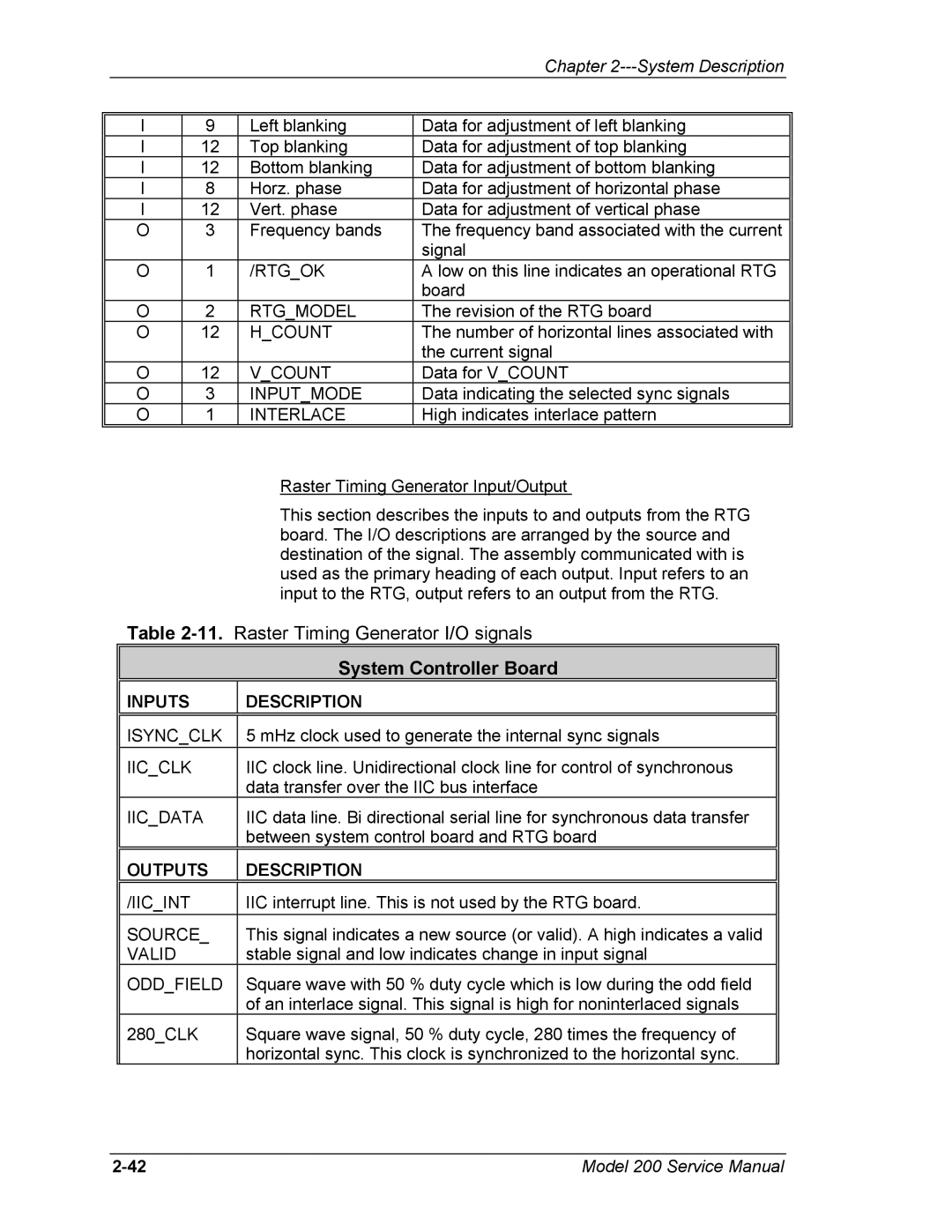
| Raster Timing Generator Input/Output |
| This section describes the inputs to and outputs from the RTG |
| board. The I/O descriptions are arranged by the source and |
| destination of the signal. The assembly communicated with is |
| used as the primary heading of each output. Input refers to an |
| input to the RTG, output refers to an output from the RTG. |
Table | |
| System Controller Board |
|
|
INPUTS | DESCRIPTION |
|
|
ISYNC_CLK | 5 mHz clock used to generate the internal sync signals |
IIC_CLK | IIC clock line. Unidirectional clock line for control of synchronous |
| data transfer over the IIC bus interface |
IIC_DATA | IIC data line. Bi directional serial line for synchronous data transfer |
| between system control board and RTG board |
|
|
OUTPUTS | DESCRIPTION |
|
|
/IIC_INT | IIC interrupt line. This is not used by the RTG board. |
SOURCE_ | This signal indicates a new source (or valid). A high indicates a valid |
VALID | stable signal and low indicates change in input signal |
ODD_FIELD | Square wave with 50 % duty cycle which is low during the odd field |
| of an interlace signal. This signal is high for noninterlaced signals |
280_CLK | Square wave signal, 50 % duty cycle, 280 times the frequency of |
| horizontal sync. This clock is synchronized to the horizontal sync. |
Model 200 Service Manual |