Chapter 2---System Description
Horizontal/Vertical Deflection Board uses these lines for proper selection of retrace times.
J13 |
|
|
|
|
|
|
|
|
| J13 | ||||
FROM | B3 | V_SYNC |
|
|
|
|
|
|
|
| ||||
|
|
|
|
|
|
|
|
|
| |||||
B4 | H_SYNC |
|
|
|
|
|
| SOURCE_VALID |
| B24 | TO | |||
VPB | B5 | G_SYNC |
|
|
|
|
|
|
| |||||
|
|
|
|
|
| ODD_FIELD |
| B23 | ||||||
|
|
|
|
|
|
|
|
|
|
|
| SCB | ||
| A5 | GRN_INPUT |
|
|
|
| ||||||||
|
|
|
|
|
|
| 280_CLK |
| B21 | |||||
|
|
|
|
|
|
|
|
|
|
|
| TO | ||
| B19 | ISYNC_CLK |
|
|
|
|
|
| CLAMP |
| B2 | |||
FROM |
|
|
|
|
|
| BLANKING |
| B1 | VPB | ||||
|
|
|
|
|
|
|
|
|
|
| ||||
|
|
|
|
|
|
|
|
|
|
|
|
| ||
SCB | B27 | IIC_CLK |
| RASTER |
|
|
|
|
|
| ||||
|
|
|
|
|
|
|
|
|
|
| ||||
| B28 | IIC_DATA |
|
|
| H_BAND0 |
| B7 |
| |||||
|
|
|
|
|
|
|
|
| ||||||
|
|
|
|
|
| TIMING |
|
|
|
| ||||
|
|
|
|
|
|
|
| H_BAND1 |
| B8 |
| |||
|
|
|
|
|
| GENERATOR |
|
| H_BAND2 |
| B9 | TO | ||
|
|
|
|
|
|
|
|
|
|
| /H_ENABLE |
| B11 | HVDB |
| A29 |
| +5.1V_STBY |
|
|
|
|
|
| H_F2V |
| B12 |
| |
|
|
|
|
|
|
| H_DRIVE |
| B16 |
| ||||
FROM | B29 |
| GND |
|
|
|
|
|
|
|
| |||
|
|
|
|
|
|
|
|
|
| |||||
A32 | +5.1V |
|
|
|
|
|
|
|
|
| TO | |||
LVPS | B32 | +5.1V |
|
|
|
|
|
| HVPS_SYNC |
| A14 | |||
|
|
|
|
|
|
|
|
|
|
|
|
|
| HVPS |
| A31 | +15V |
|
|
|
|
|
|
|
|
| |||
|
|
|
|
|
|
|
|
|
|
| ||||
| B31 | +15V |
|
|
|
|
|
|
|
|
| TO | ||
|
|
|
|
|
|
|
|
|
|
| V_DRIVE |
| B15 | |
| A30 |
|
|
|
|
|
|
|
|
|
| CDB | ||
| B30 |
|
|
|
|
|
|
|
|
| ||||
|
|
|
|
|
|
|
|
|
|
| ||||
|
|
|
|
|
|
|
|
|
|
|
|
|
|
|
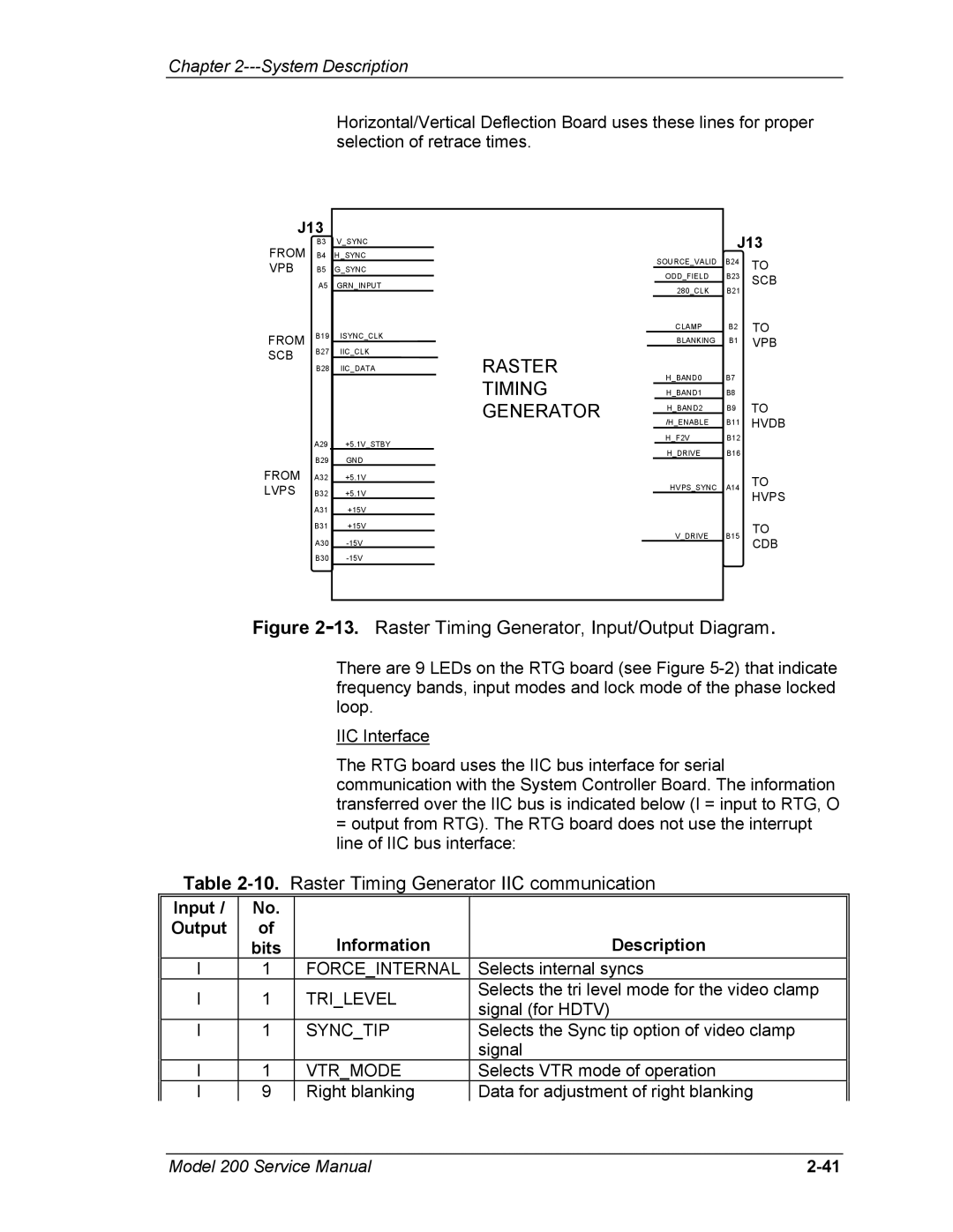
Figure 2-13. Raster Timing Generator, Input/Output Diagram.
There are 9 LEDs on the RTG board (see Figure
IIC Interface
The RTG board uses the IIC bus interface for serial communication with the System Controller Board. The information transferred over the IIC bus is indicated below (I = input to RTG, O
=output from RTG). The RTG board does not use the interrupt line of IIC bus interface:
Table 2-10. Raster Timing Generator IIC communication
Input / | No. |
|
| |
Output | of | Information | Description | |
| bits | |||
I | 1 | FORCE_INTERNAL | Selects internal syncs | |
I | 1 | TRI_LEVEL | Selects the tri level mode for the video clamp | |
signal (for HDTV) | ||||
|
|
| ||
I | 1 | SYNC_TIP | Selects the Sync tip option of video clamp | |
|
|
| signal | |
I | 1 | VTR_MODE | Selects VTR mode of operation | |
I | 9 | Right blanking | Data for adjustment of right blanking |
Model 200 Service Manual |