Chapter
5.0 Troubleshooting
Contents
5.1 | Status LEDs | |
5.2 | Error Codes | |
5.3 | Troubleshooting Guide |
5.1 Status LEDs
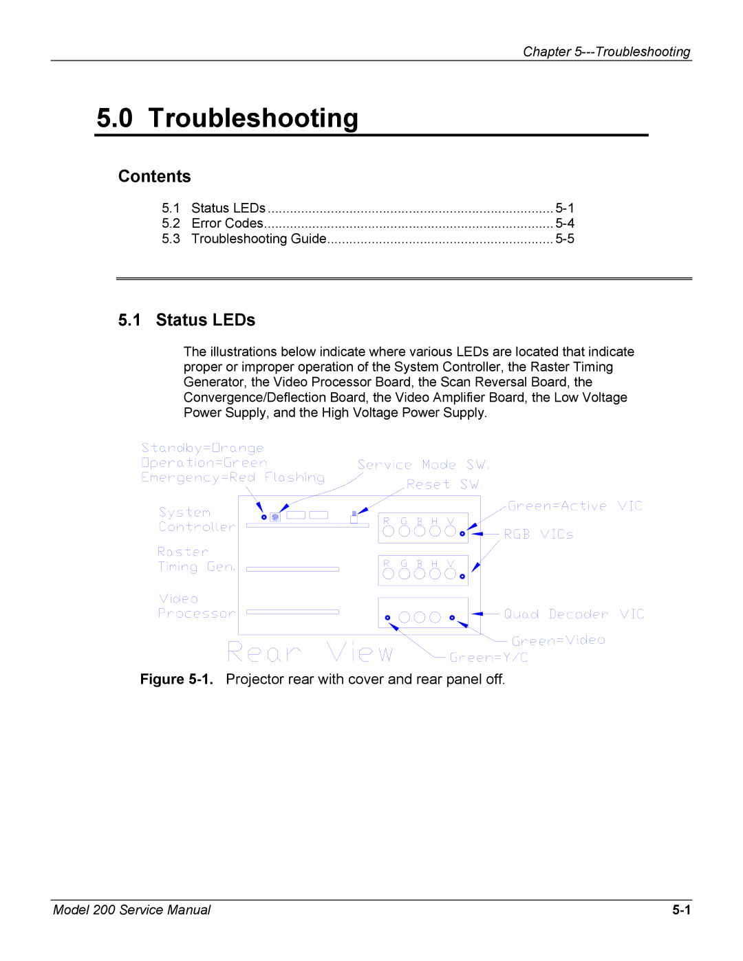
The illustrations below indicate where various LEDs are located that indicate proper or improper operation of the System Controller, the Raster Timing Generator, the Video Processor Board, the Scan Reversal Board, the Convergence/Deflection Board, the Video Amplifier Board, the Low Voltage Power Supply, and the High Voltage Power Supply.
Figure 5-1. Projector rear with cover and rear panel off.
Model 200 Service Manual |