|
|
|
| Chapter | ||
|
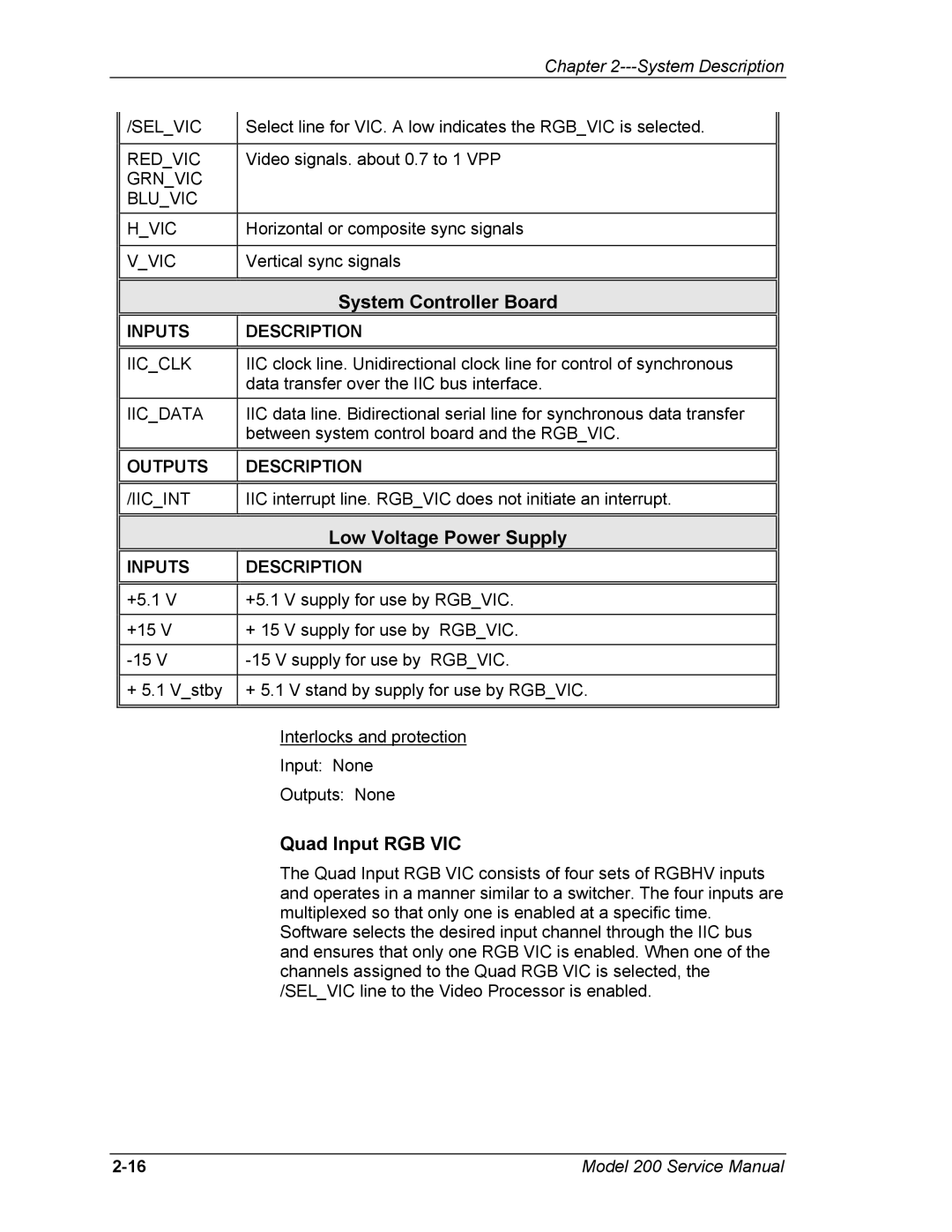
| /SEL_VIC |
| Select line for VIC. A low indicates the RGB_VIC is selected. |
|
|
|
|
|
|
| ||
|
|
|
|
|
|
|
|
| RED_VIC |
| Video signals. about 0.7 to 1 VPP |
|
|
|
| GRN_VIC |
|
|
|
|
|
| BLU_VIC |
|
|
|
|
|
| H_VIC |
| Horizontal or composite sync signals |
|
|
|
|
|
|
|
|
|
|
| V_VIC |
| Vertical sync signals |
|
|
|
|
|
|
|
|
|
|
|
|
|
|
|
|
|
|
|
| System Controller Board |
|
|
|
|
|
|
|
| |
|
| INPUTS |
| DESCRIPTION |
|
|
|
|
|
|
|
|
|
|
|
|
|
|
| |
|
| IIC_CLK |
| IIC clock line. Unidirectional clock line for control of synchronous |
|
|
|
|
|
| data transfer over the IIC bus interface. |
|
|
|
| IIC_DATA |
| IIC data line. Bidirectional serial line for synchronous data transfer |
|
|
|
|
|
| between system control board and the RGB_VIC. |
|
|
|
|
|
|
|
| |
|
| OUTPUTS |
| DESCRIPTION |
|
|
|
|
|
|
|
|
|
|
|
|
|
|
| |
|
| /IIC_INT |
| IIC interrupt line. RGB_VIC does not initiate an interrupt. |
|
|
|
|
|
|
|
|
|
|
|
|
|
|
| |
|
|
|
| Low Voltage Power Supply |
|
|
|
|
|
|
|
| |
|
| INPUTS |
| DESCRIPTION |
|
|
|
|
|
|
|
|
|
|
|
|
|
|
| |
|
| +5.1 V |
| +5.1 V supply for use by RGB_VIC. |
|
|
|
|
|
|
|
|
|
|
| +15 V |
| + 15 V supply for use by RGB_VIC. |
|
|
|
|
|
|
|
|
|
|
|
|
|
| ||
|
|
|
|
|
|
|
|
| + 5.1 V_stby |
| + 5.1 V stand by supply for use by RGB_VIC. |
|
|
|
|
|
|
|
|
|
|
|
|
|
|
|
|
Interlocks and protection
Input: None
Outputs: None
Quad Input RGB VIC
The Quad Input RGB VIC consists of four sets of RGBHV inputs and operates in a manner similar to a switcher. The four inputs are multiplexed so that only one is enabled at a specific time. Software selects the desired input channel through the IIC bus and ensures that only one RGB VIC is enabled. When one of the channels assigned to the Quad RGB VIC is selected, the /SEL_VIC line to the Video Processor is enabled.
Model 200 Service Manual |