Chapter 2---System Description
|
|
|
|
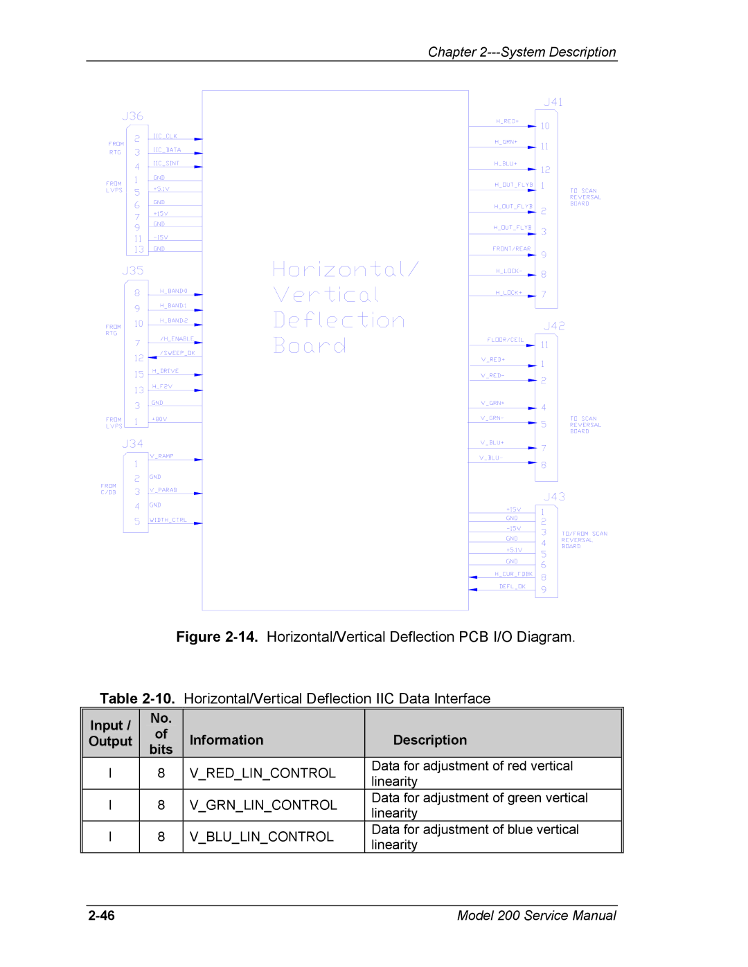
| Figure | Horizontal/Vertical Deflection PCB I/O Diagram. | |||||
| Table | ||||||||||
| Input / |
|
| No. |
|
|
|
|
|
|
|
|
|
| of |
|
| Information |
|
| Description |
| |
| Output |
|
|
|
|
|
|
| |||
|
|
| bits |
|
|
|
|
| |||
|
|
|
|
|
|
|
|
|
|
| |
| I | 8 |
| V_RED_LIN_CONTROL |
| Data for adjustment of red vertical | |||||
|
|
| linearity | ||||||||
|
|
|
|
|
|
|
|
|
| ||
| I | 8 |
| V_GRN_LIN_CONTROL |
| Data for adjustment of green vertical | |||||
|
|
| linearity | ||||||||
|
|
|
|
|
|
|
|
|
| ||
| I | 8 |
| V_BLU_LIN_CONTROL |
| Data for adjustment of blue vertical | |||||
|
|
| linearity | ||||||||
|
|
|
|
|
|
|
|
|
| ||
Model 200 Service Manual |
