Chapter 2---System Description
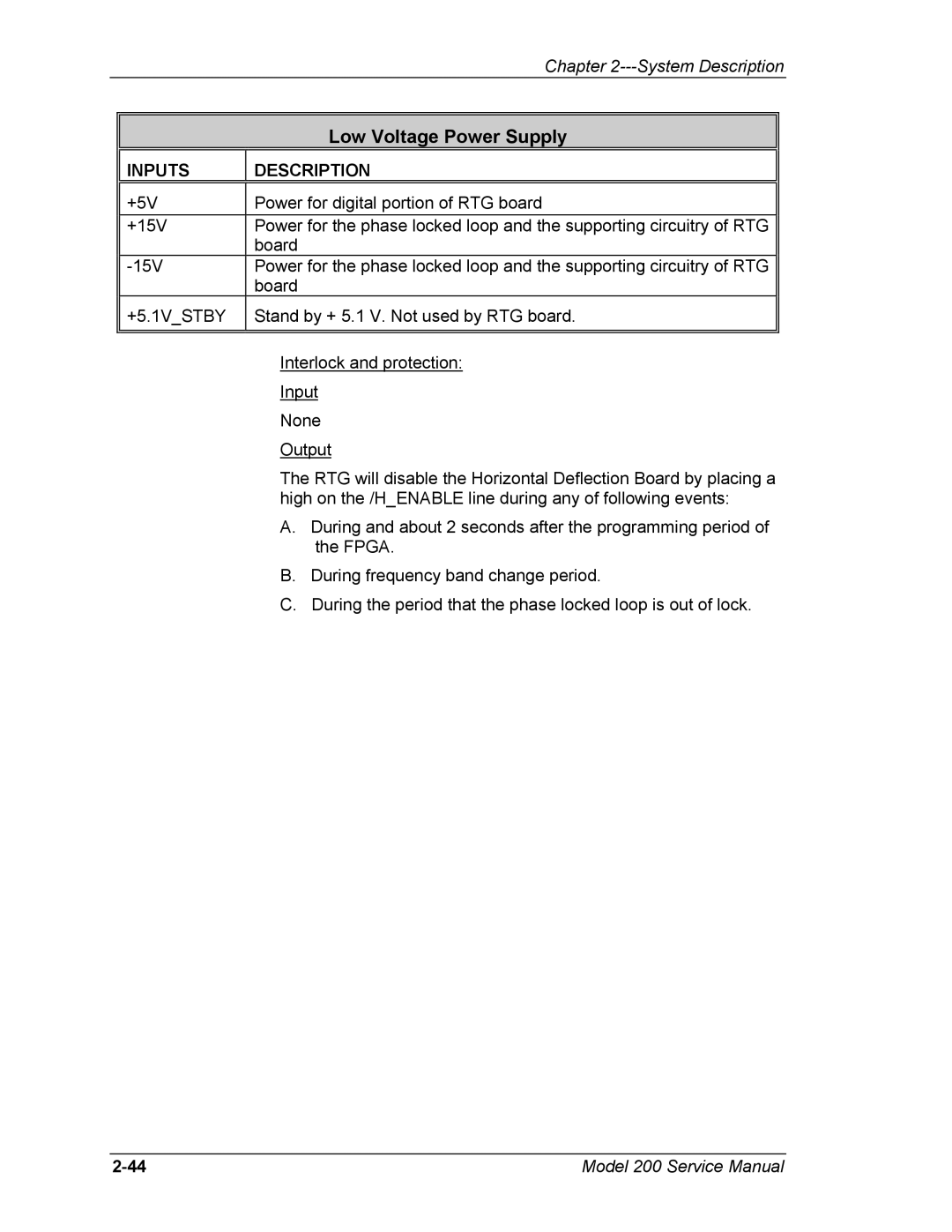
Low Voltage Power Supply
INPUTS
DESCRIPTION
+5V | Power for digital portion of RTG board |
+15V | Power for the phase locked loop and the supporting circuitry of RTG |
| board |
Power for the phase locked loop and the supporting circuitry of RTG | |
| board |
+5.1V_STBY | Stand by + 5.1 V. Not used by RTG board. |
|
|
Interlock and protection:
Input
None
Output
The RTG will disable the Horizontal Deflection Board by placing a high on the /H_ENABLE line during any of following events:
A.During and about 2 seconds after the programming period of the FPGA.
B.During frequency band change period.
C.During the period that the phase locked loop is out of lock.
Model 200 Service Manual |