Chapter 4---Maintenance (Removal/Replacement)
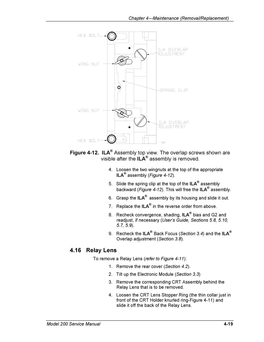
Figure 4-12. ILA® Assembly top view. The overlap screws shown are
visible after the ILA® assembly is removed.
4.Loosen the two wingnuts at the top of the appropriate ILA® assembly (Figure
5.Slide the spring clip at the top of the ILA® assembly backward (Figure
6.Grasp the ILA® assembly by its housing and slide it out.
7.Replace the ILA® in the reverse order from above.
8.Recheck convergence, shading, ILA® bias and G2 and readjust, if necessary (User’s Guide, Sections 5.8, 5.10, 5.7, 5.9).
9.Recheck the ILA® Back Focus (Section 3.4) and the ILA® Overlap adjustment (Section 3.8).
4.16Relay Lens
To remove a Relay Lens (refer to Figure
1.Remove the rear cover (Section 4.2).
2.Tilt up the Electronic Module (Section 3.3)
3.Remove the corresponding CRT Assembly behind the Relay Lens that is to be removed.
4.Loosen the CRT Lens Stopper Ring (the thin collar just in front of the CRT Holder knurled
Model 200 Service Manual |