Chapter 2---System Description
2.3.11 Backplane PCB
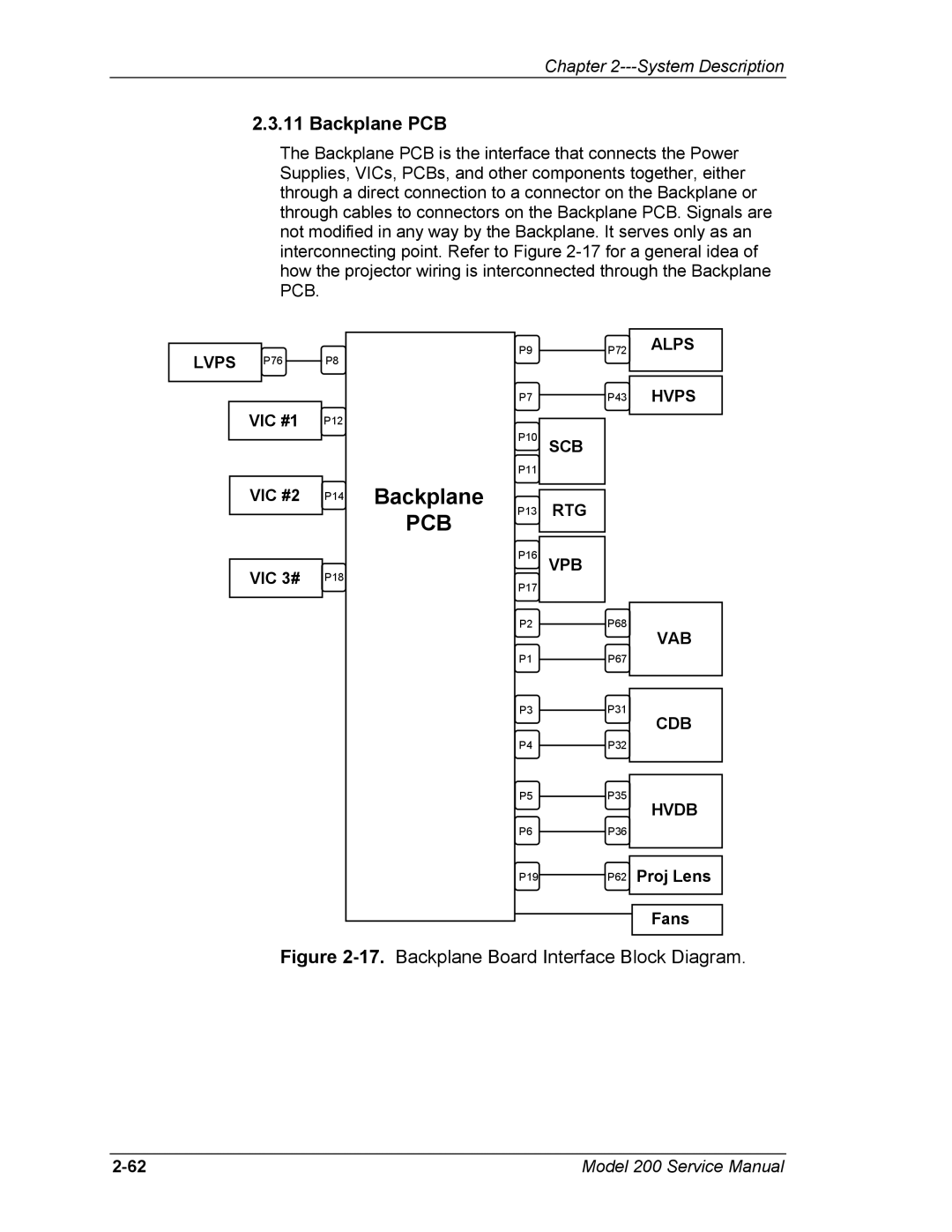
The Backplane PCB is the interface that connects the Power Supplies, VICs, PCBs, and other components together, either through a direct connection to a connector on the Backplane or through cables to connectors on the Backplane PCB. Signals are not modified in any way by the Backplane. It serves only as an interconnecting point. Refer to Figure
LVPS P76
VIC #1
VIC #2
VIC 3#
P8
P12
P14
P18
Backplane
PCB
P9
P7
P10
P11
P13
P16
P17
P2
P1
P3
P4
P5
P6
P19
P72 | ALPS |
P43 | HVPS |
SCB
RTG
VPB
P68
VAB
P67
P31
CDB
P32
P35
HVDB
P36
P62 Proj Lens
Fans
Figure 2-17. Backplane Board Interface Block Diagram.
Model 200 Service Manual |