Chapter 2---System Description
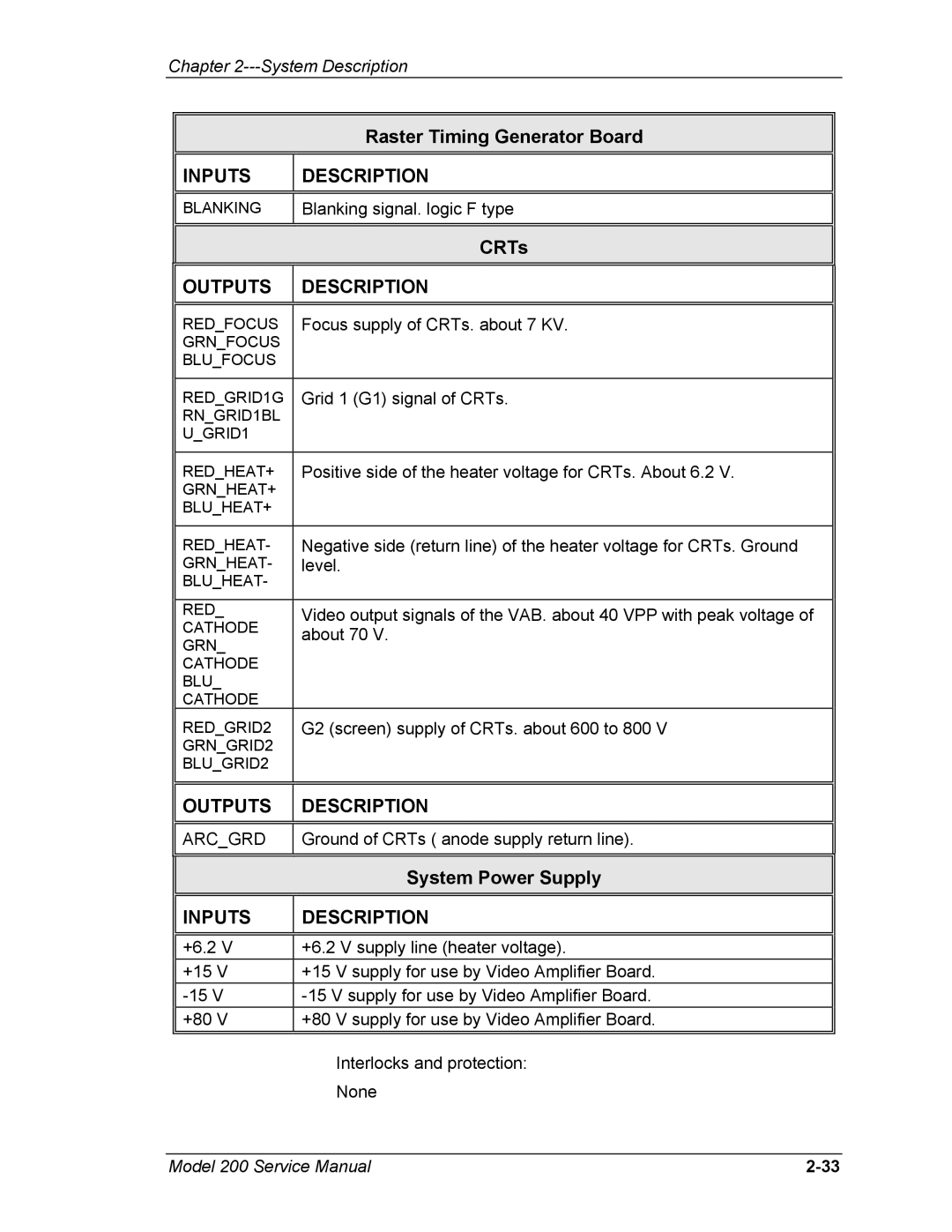
Raster Timing Generator Board
INPUTS | DESCRIPTION |
BLANKING
Blanking signal. logic F type
CRTs
OUTPUTS | DESCRIPTION |
|
|
|
|
|
|
|
RED_FOCUS | Focus supply of CRTs. about 7 KV. |
|
GRN_FOCUS |
|
|
BLU_FOCUS |
|
|
|
|
|
RED_GRID1G | Grid 1 (G1) signal of CRTs. |
|
RN_GRID1BL |
|
|
U_GRID1 |
|
|
|
|
|
RED_HEAT+ | Positive side of the heater voltage for CRTs. About 6.2 V. |
|
GRN_HEAT+ |
|
|
BLU_HEAT+ |
|
|
|
|
|
RED_HEAT- | Negative side (return line) of the heater voltage for CRTs. Ground |
|
GRN_HEAT- | level. |
|
BLU_HEAT- |
|
|
|
|
|
RED_ | Video output signals of the VAB. about 40 VPP with peak voltage of |
|
CATHODE | about 70 V. |
|
GRN_ |
| |
|
| |
CATHODE |
|
|
BLU_ |
|
|
CATHODE |
|
|
RED_GRID2 | G2 (screen) supply of CRTs. about 600 to 800 V |
|
GRN_GRID2 |
|
|
BLU_GRID2 |
|
|
|
|
|
| OUTPUTS | DESCRIPTION |
|
|
|
|
|
|
| ARC_GRD | Ground of CRTs ( anode supply return line). |
|
|
|
|
|
|
|
| System Power Supply |
|
|
|
| INPUTS | DESCRIPTION |
|
|
|
| +6.2 V | +6.2 V supply line (heater voltage). |
| +15 V | +15 V supply for use by Video Amplifier Board. |
| ||
| +80 V | +80 V supply for use by Video Amplifier Board. |
|
|
|
Interlocks and protection:
None
Model 200 Service Manual |
