|
|
| Chapter | |
|
|
|
|
|
| I | TINT | Data for adjustment of Hue |
|
|
|
|
|
|
| I | COLOR | Data for adjustment of color |
|
|
|
|
|
|
| I | SHARP | Data for adjustment of Sharpness |
|
|
|
|
|
|
| I | VTR | Selection of VTR mode |
|
|
|
|
|
|
| O | VNR | Selection of Video Noise Reduction mode |
|
|
|
|
|
|
|
|
|
|
|
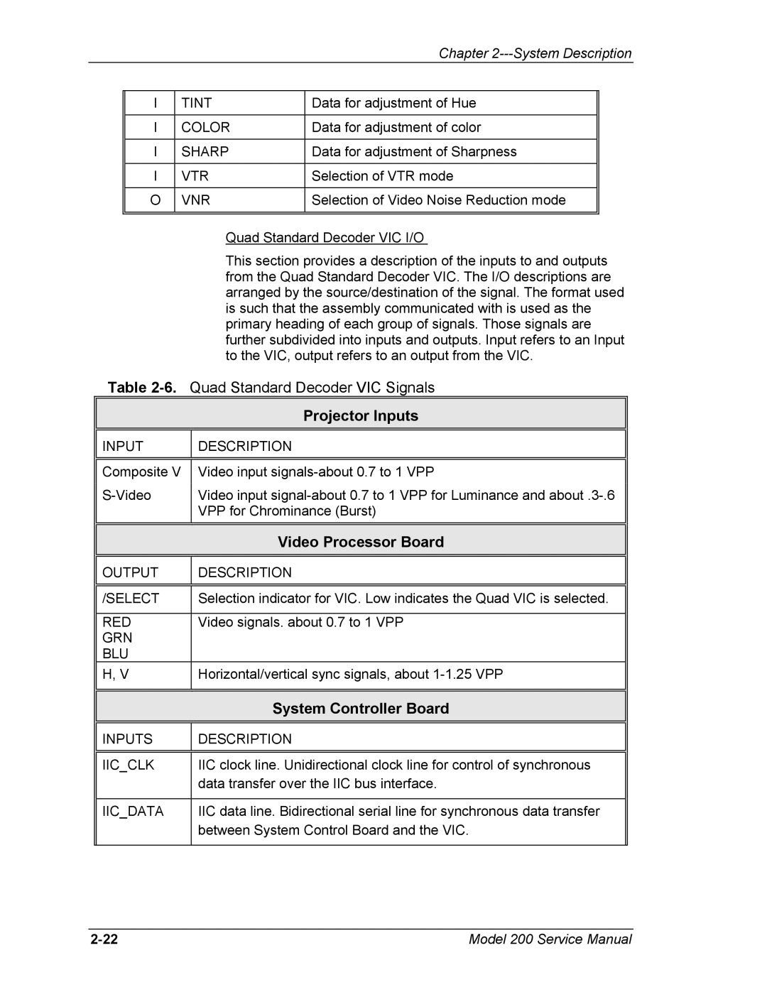
| Quad Standard Decoder VIC I/O |
| This section provides a description of the inputs to and outputs |
| from the Quad Standard Decoder VIC. The I/O descriptions are |
| arranged by the source/destination of the signal. The format used |
| is such that the assembly communicated with is used as the |
| primary heading of each group of signals. Those signals are |
| further subdivided into inputs and outputs. Input refers to an Input |
| to the VIC, output refers to an output from the VIC. |
Table | |
| Projector Inputs |
|
|
INPUT | DESCRIPTION |
|
|
| |
Composite V | Video input |
Video input | |
| VPP for Chrominance (Burst) |
|
|
| Video Processor Board |
|
|
OUTPUT | DESCRIPTION |
|
|
|
|
/SELECT | Selection indicator for VIC. Low indicates the Quad VIC is selected. |
|
|
RED | Video signals. about 0.7 to 1 VPP |
GRN |
|
BLU |
|
H, V | Horizontal/vertical sync signals, about |
|
|
|
|
| System Controller Board |
|
|
INPUTS | DESCRIPTION |
|
|
|
|
IIC_CLK | IIC clock line. Unidirectional clock line for control of synchronous |
| data transfer over the IIC bus interface. |
|
|
IIC_DATA | IIC data line. Bidirectional serial line for synchronous data transfer |
| between System Control Board and the VIC. |
|
|
Model 200 Service Manual |