Chapter 4---Maintenance (Removal/Replacement)
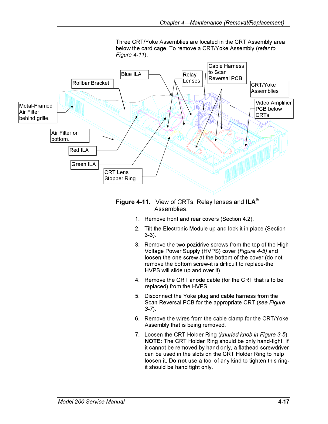
Three CRT/Yoke Assemblies are located in the CRT Assembly area below the card cage. To remove a CRT/Yoke Assembly (refer to Figure
Blue ILA
Rollbar Bracket
Air Filter on bottom.
Red ILA
Green ILA
CRT Lens
Stopper Ring
Relay Lenses
Cable Harness to Scan Reversal PCB
CRT/Yoke
Assemblies
Video Amplifier
PCB below
CRTs
Figure 4-11. View of CRTs, Relay lenses and ILA® Assemblies.
1.Remove front and rear covers (Section 4.2).
2.Tilt the Electronic Module up and lock it in place (Section
3.Remove the two pozidrive screws from the top of the High Voltage Power Supply (HVPS) cover (Figure
4.Remove the CRT anode cable (for the CRT that is to be replaced) from the HVPS.
5.Disconnect the Yoke plug and cable harness from the Scan Reversal PCB for the appropriate CRT (see Figure
6.Remove the wires from the cable clamp for the CRT/Yoke Assembly that is being removed.
7.Loosen the CRT Holder Ring (knurled knob in Figure
Model 200 Service Manual |