Chapter 2---System Description
•Tint, sharpness, and color adjustment
•LED indication of Composite or
•IIC serial bus interface
Comp
Yin C in
IIC_CLK
IIC_DATA
+5.1V
+15V
B2 R
B4 G
B6 B
B8 /H
B10 /V
B13
A13
B16 | B12 | /SELECT | |
|
| ||
B15 |
|
|
|
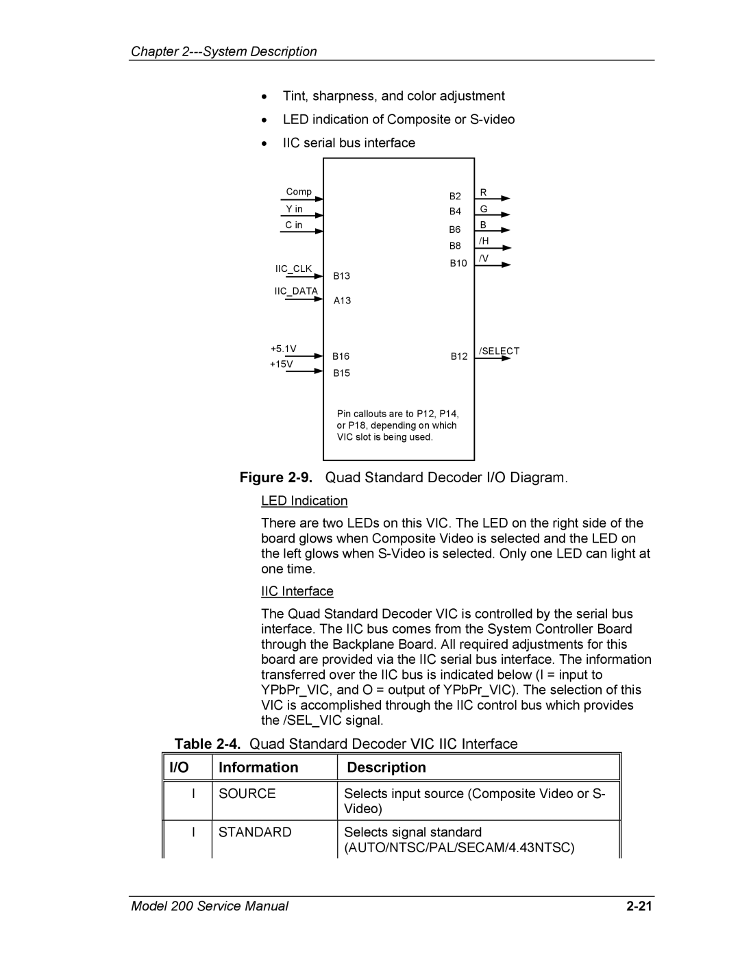
Pin callouts are to P12, P14, or P18, depending on which VIC slot is being used.
Figure 2-9. Quad Standard Decoder I/O Diagram.
LED Indication
There are two LEDs on this VIC. The LED on the right side of the board glows when Composite Video is selected and the LED on the left glows when
IIC Interface
The Quad Standard Decoder VIC is controlled by the serial bus interface. The IIC bus comes from the System Controller Board through the Backplane Board. All required adjustments for this board are provided via the IIC serial bus interface. The information transferred over the IIC bus is indicated below (I = input to YPbPr_VIC, and O = output of YPbPr_VIC). The selection of this VIC is accomplished through the IIC control bus which provides the /SEL_VIC signal.
Table
I/O
Information
Description
I
SOURCE
Selects input source (Composite Video or S- Video)
I
STANDARD
Selects signal standard (AUTO/NTSC/PAL/SECAM/4.43NTSC)
Model 200 Service Manual |