Chapter 2---System Description
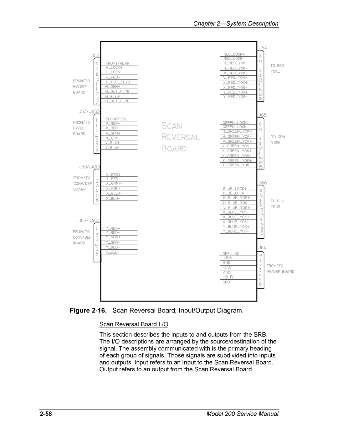
Figure 2-16. Scan Reversal Board, Input/Output Diagram.
Scan Reversal Board I /O
This section describes the inputs to and outputs from the SRB. The I/O descriptions are arranged by the source/destination of the signal. The assembly communicated with is the primary heading of each group of signals. Those signals are subdivided into inputs and outputs. Input refers to an Input to the Scan Reversal Board. Output refers to an output from the Scan Reversal Board.
Model 200 Service Manual |