Chapter 4---Maintenance (Removal/Replacement)
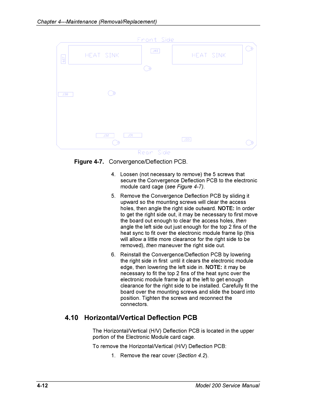
Figure 4-7. Convergence/Deflection PCB.
4.Loosen (not necessary to remove) the 5 screws that secure the Convergence Deflection PCB to the electronic module card cage (see Figure
5.Remove the Convergence Deflection PCB by sliding it upward so the mounting screws will clear the access holes, then angle the right side outward. NOTE: In order to get the right side out, it may be necessary to first move the board out enough to clear the access holes, then angle the left side out just enough for the top 2 fins of the heat sync to fit over the electronic module frame lip (this will allow a little more clearance for the right side to be removed), then maneuver the right side out.
6.Reinstall the Convergence/Deflection PCB by lowering the right side in first until it clears the electronic module edge, then lowering the left side in. NOTE: it may be necessary to fit the top 2 fins of the heat sync over the electronic module frame lip at the left to get enough clearance for the right side to be installed. Carefully fit the board over the mounting screws and slide the board into position. Tighten the screws and reconnect the connectors.
4.10Horizontal/Vertical Deflection PCB
The Horizontal/Vertical (H/V) Deflection PCB is located in the upper portion of the Electronic Module card cage.
To remove the Horizontal/Vertical (H/V) Deflection PCB:
1. Remove the rear cover (Section 4.2).
Model 200 Service Manual |