Chapter 4---Maintenance (Removal/Replacement)
7.Place the Green CRT Assembly in a safe location on or against one of the other CRT Assemblies.
8.Disconnect the Red and Blue CRT Socket Connectors and gently lay them on the top of the Video Amplifier Board.
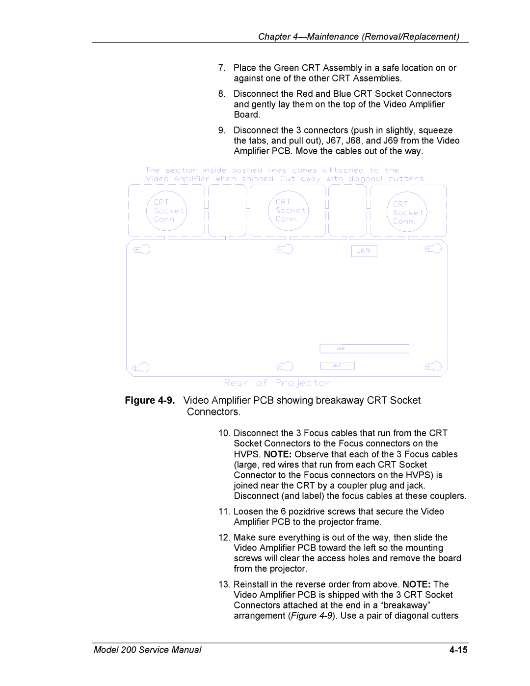
9.Disconnect the 3 connectors (push in slightly, squeeze the tabs, and pull out), J67, J68, and J69 from the Video Amplifier PCB. Move the cables out of the way.
Figure 4-9. Video Amplifier PCB showing breakaway CRT Socket Connectors.
10.Disconnect the 3 Focus cables that run from the CRT Socket Connectors to the Focus connectors on the HVPS. NOTE: Observe that each of the 3 Focus cables (large, red wires that run from each CRT Socket Connector to the Focus connectors on the HVPS) is joined near the CRT by a coupler plug and jack. Disconnect (and label) the focus cables at these couplers.
11.Loosen the 6 pozidrive screws that secure the Video Amplifier PCB to the projector frame.
12.Make sure everything is out of the way, then slide the Video Amplifier PCB toward the left so the mounting screws will clear the access holes and remove the board from the projector.
13.Reinstall in the reverse order from above. NOTE: The Video Amplifier PCB is shipped with the 3 CRT Socket Connectors attached at the end in a “breakaway” arrangement (Figure
Model 200 Service Manual |