|
|
|
| Chapter |
|
|
|
|
|
| I | RED_G2 | Red G2 Control | |
|
|
|
|
|
| I | GRN_G2 | Green G2 Control | |
|
|
|
|
|
| I | BLU_G2 | Blue G2 Control | |
|
|
|
|
|
| I | WHT_BOOST | Gamma correction | |
|
|
|
|
|
| I | BLK_BOOST | Gamma correction | |
|
|
|
|
|
| I | G1_BIAS | G1 bias level | |
|
|
|
|
|
| O | /VA_OK | Issues to SCB that Video Amplifier | |
|
|
|
| is OK |
|
|
|
|
|
| O | BEAM_CURRENT | Beam current control | |
|
|
|
|
|
| O | OK_DETECT | Issues to SCB that VPB is OK | |
|
|
|
|
|
|
|
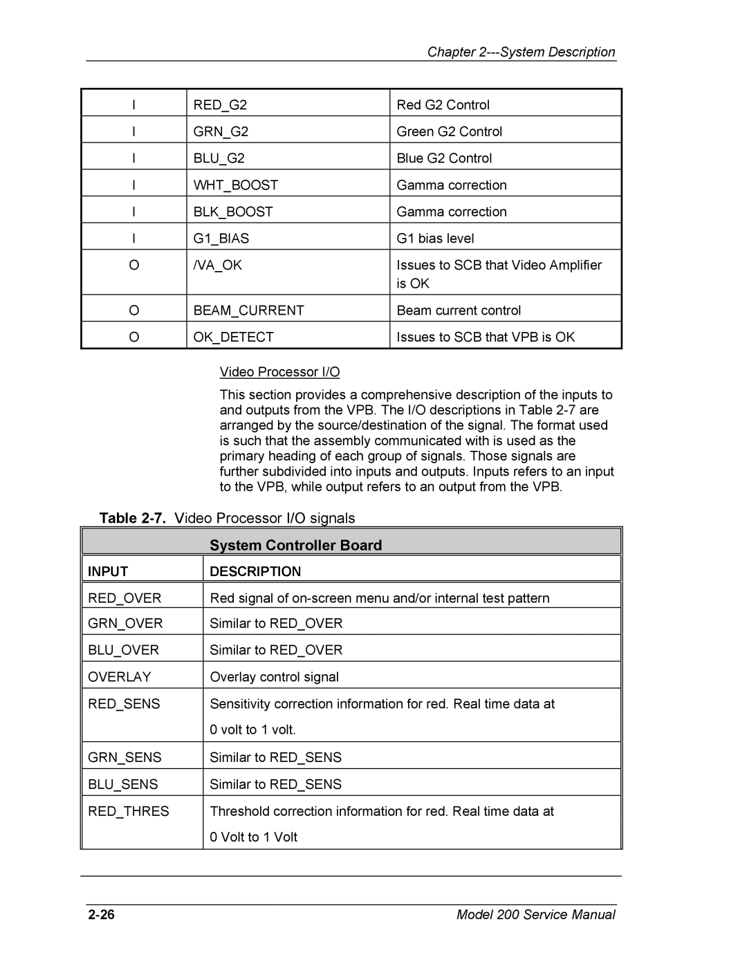
| Video Processor I/O |
|
|
|
| This section provides a comprehensive description of the inputs to | |
|
|
| and outputs from the VPB. The I/O descriptions in Table | |
|
|
| arranged by the source/destination of the signal. The format used | |
|
|
| is such that the assembly communicated with is used as the | |
|
|
| primary heading of each group of signals. Those signals are | |
|
|
| further subdivided into inputs and outputs. Inputs refers to an input | |
|
|
| to the VPB, while output refers to an output from the VPB. | |
| Table |
| ||
|
|
| System Controller Board |
|
|
|
|
|
|
| INPUT |
| DESCRIPTION |
|
|
|
|
| |
| RED_OVER |
| Red signal of | |
| GRN_OVER |
| Similar to RED_OVER |
|
|
|
|
|
|
| BLU_OVER |
| Similar to RED_OVER |
|
|
|
|
|
|
| OVERLAY |
| Overlay control signal |
|
|
|
|
| |
| RED_SENS |
| Sensitivity correction information for red. Real time data at | |
|
|
| 0 volt to 1 volt. |
|
|
|
|
|
|
| GRN_SENS |
| Similar to RED_SENS |
|
|
|
|
|
|
| BLU_SENS |
| Similar to RED_SENS |
|
|
|
|
| |
| RED_THRES |
| Threshold correction information for red. Real time data at | |
|
|
| 0 Volt to 1 Volt |
|
|
|
|
|
|
|
|
|
|
|
|
|
|
|
|
Model 200 Service Manual |