Chapter 2---System Description
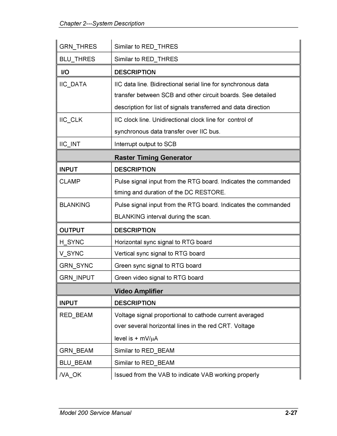
GRN_THRES | Similar to RED_THRES |
|
|
BLU_THRES | Similar to RED_THRES |
|
|
|
|
I/O | DESCRIPTION |
|
|
IIC_DATA | IIC data line. Bidirectional serial line for synchronous data |
| transfer between SCB and other circuit boards. See detailed |
| description for list of signals transferred and data direction |
|
|
IIC_CLK | IIC clock line. Unidirectional clock line for control of |
| synchronous data transfer over IIC bus. |
|
|
IIC_INT | Interrupt output to SCB |
|
|
|
|
|
| Raster Timing Generator |
|
|
|
|
|
| INPUT | DESCRIPTION |
|
|
|
|
|
| CLAMP | Pulse signal input from the RTG board. Indicates the commanded |
|
|
| timing and duration of the DC RESTORE. |
|
|
|
|
|
| BLANKING | Pulse signal input from the RTG board. Indicates the commanded |
|
|
| BLANKING interval during the scan. |
|
|
|
|
|
|
|
|
|
| OUTPUT | DESCRIPTION |
|
|
|
|
|
| H_SYNC | Horizontal sync signal to RTG board |
|
| V_SYNC | Vertical sync signal to RTG board |
|
|
|
|
|
| GRN_SYNC | Green sync signal to RTG board |
|
|
|
|
|
| GRN_INPUT | Green video signal to RTG board |
|
|
|
|
|
|
|
|
|
|
| Video Amplifier |
|
|
|
|
|
| INPUT | DESCRIPTION |
|
|
|
|
|
| RED_BEAM | Voltage signal proportional to cathode current averaged |
|
|
| over several horizontal lines in the red CRT. Voltage |
|
|
| level is + mV/∝A |
|
|
|
|
|
| GRN_BEAM | Similar to RED_BEAM |
|
|
|
|
|
| BLU_BEAM | Similar to RED_BEAM |
|
|
|
|
|
| /VA_OK | Issued from the VAB to indicate VAB working properly |
|
|
|
|
|
Model 200 Service Manual |