Chapter 2---System Description
LED indication
The RGB VIC includes an LED which glows when the board is selected (i.e. when the /SEL_CH line is low) as the input for the Model 200 Projector.
IIC serial bus interface section
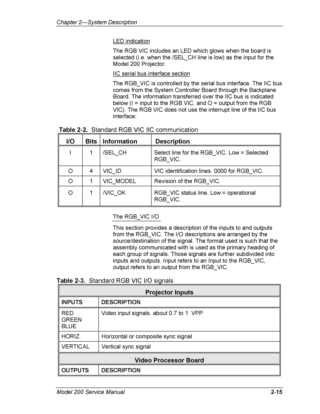
The RGB_VIC is controlled by the serial bus interface. The IIC bus comes from the System Controller Board through the Backplane Board. The information transferred over the IIC bus is indicated below (I = input to the RGB VIC, and O = output from the RGB VIC). The RGB VIC does not use the interrupt line of the IIC bus interface:
Table
I/O | Bits | Information | Description |
|
|
|
|
I | 1 | /SEL_CH | Select line for the RGB_VIC. Low = Selected |
|
|
| RGB_VIC. |
|
|
|
|
O | 4 | VIC_ID | VIC identification lines. 0000 for RGB_VIC. |
|
|
|
|
O | 1 | VIC_MODEL | Revision of the RGB_VIC. |
|
|
|
|
O | 1 | /VIC_OK | RGB_VIC status line. Low = operational |
|
|
| RGB_VIC. |
|
|
|
|
|
|
|
|
The RGB_VIC I/O
This section provides a description of the inputs to and outputs from the RGB_VIC. The I/O descriptions are arranged by the source/destination of the signal. The format used is such that the assembly communicated with is used as the primary heading of each group of signals. Those signals are further subdivided into inputs and outputs. Input refers to an Input to the RGB_VIC, output refers to an output from the RGB_VIC.
Table
Projector Inputs
INPUTS
DESCRIPTION
RED | Video input signals. about 0.7 to 1 VPP |
GREEN |
|
BLUE |
|
HORIZ. | Horizontal or composite sync signal |
|
|
VERTICAL | Vertical sync signal |
|
|
Video Processor Board
OUTPUTS
DESCRIPTION
Model 200 Service Manual |