Chapter 2---System Description
2.3.10 Scan Reversal Board
The Scan Reversal Board (SRB) is mounted vertically on the right side of the card cage.
The following functions are provided by the SRB:
•Reversal of scan in both horizontal and vertical axes
•Horizontal width adjustment for each color (R, G &B)
•Horizontal current feedback
•Scan failure detection for all six main (horizontal and vertical) deflection amplifiers
The Scan Reversal Board Input/Output diagram (Figure
The SRB does not require any IIC bus interface.
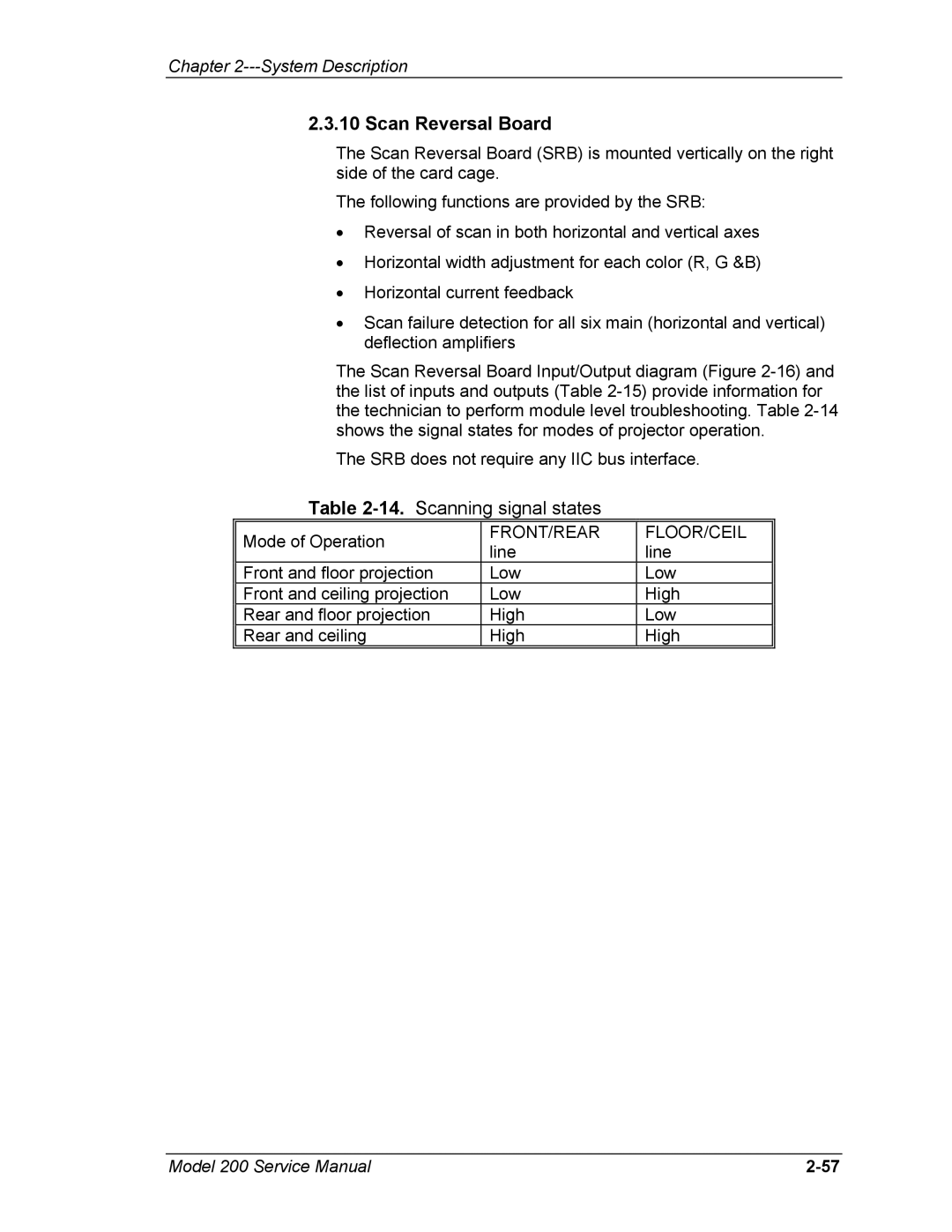
Table 2-14. Scanning signal states
Mode of Operation | FRONT/REAR | FLOOR/CEIL | |
line | line | ||
| |||
Front and floor projection | Low | Low | |
Front and ceiling projection | Low | High | |
Rear and floor projection | High | Low | |
Rear and ceiling | High | High | |
|
|
|
Model 200 Service Manual |