Section 3 - Detailed Components Description
RE-2 Receiver Controls, Connectors, and Indicators
| 1 | 2 |
|
| 3 |
power | GPA CH |
| - 3 | 0 +3 | |
R | 12u 05 |
|
|
|
|
2 |
|
|
|
| |
E V |
|
|
|
| |
set | AU DIO |
| 1 3 10 | 30 | 100 |
3
8 | 5 |
|
|
|
| Balanced | U.S. Patent No. 6,256,484 | ||
| Audio | |||
|
|
|
| |
|
|
| ||
AC/DC |
|
|
| |
+ | - |
|
|
|
|
| Mic | Line Line | High |
|
|
| Level | Z |
4 |
|
|
| 6 |
| Antenna |
Tested to Comply |
|
with FCC Standards |
|
CANADA XXXXXX |
|
S.N. 8A |
|
Telex Communications, Inc. | Made in U.S.A. |
7
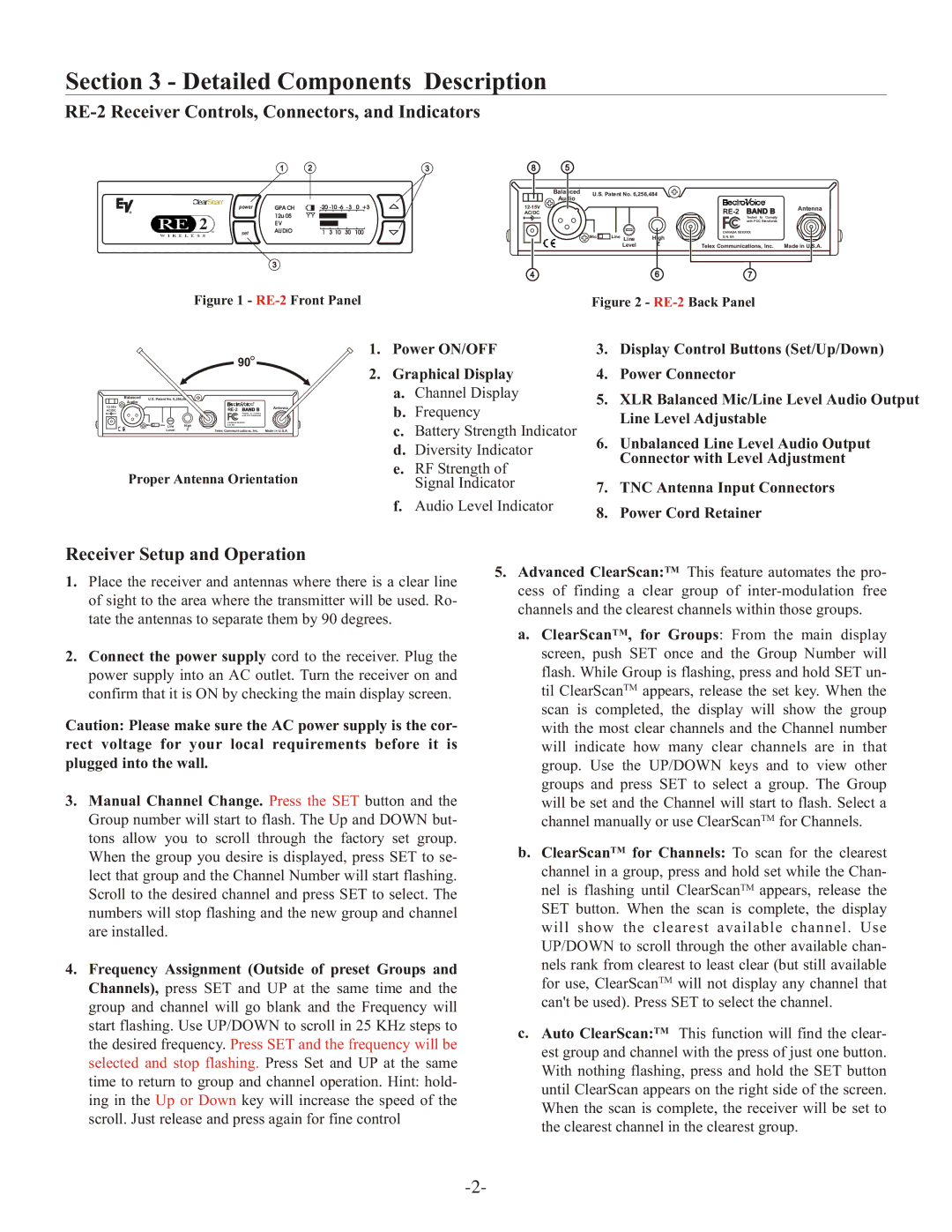
Figure 1 - RE-2 Front Panel
Figure 2 - RE-2 Back Panel
|
|
|
|
| 90 |
|
| Balanced | U.S. Patent No. 6,256,48 |
|
| ||
| Audio |
|
|
|
|
|
|
|
|
| Antenna | ||
AC/DC |
|
|
|
| ||
+ | - |
|
|
| Tested to Comply |
|
|
|
| with FCC Standards |
| ||
|
| Mic | Line Line | High | CANADA XXXXXX |
|
|
| S.N. 8A |
| |||
|
|
| Level | Z | Telex Communications, Inc. | Made in U.S.A. |
Proper Antenna Orientation
1.Power ON/OFF
2.Graphical Display
a.Channel Display
b.Frequency
c.Battery Strength Indicator
d.Diversity Indicator
e.RF Strength of Signal Indicator
f.Audio Level Indicator
3.Display Control Buttons (Set/Up/Down)
4.Power Connector
5.XLR Balanced Mic/Line Level Audio Output Line Level Adjustable
6.Unbalanced Line Level Audio Output Connector with Level Adjustment
7.TNC Antenna Input Connectors
8.Power Cord Retainer
Receiver Setup and Operation
1.Place the receiver and antennas where there is a clear line of sight to the area where the transmitter will be used. Ro- tate the antennas to separate them by 90 degrees.
2.Connect the power supply cord to the receiver. Plug the power supply into an AC outlet. Turn the receiver on and confirm that it is ON by checking the main display screen.
Caution: Please make sure the AC power supply is the cor- rect voltage for your local requirements before it is plugged into the wall.
3.Manual Channel Change. Press the SET button and the Group number will start to flash. The Up and DOWN but- tons allow you to scroll through the factory set group. When the group you desire is displayed, press SET to se- lect that group and the Channel Number will start flashing. Scroll to the desired channel and press SET to select. The numbers will stop flashing and the new group and channel are installed.
4.Frequency Assignment (Outside of preset Groups and Channels), press SET and UP at the same time and the group and channel will go blank and the Frequency will start flashing. Use UP/DOWN to scroll in 25 KHz steps to the desired frequency. Press SET and the frequency will be selected and stop flashing. Press Set and UP at the same time to return to group and channel operation. Hint: hold- ing in the Up or Down key will increase the speed of the scroll. Just release and press again for fine control
5.Advanced ClearScan:TM This feature automates the pro- cess of finding a clear group of
a.ClearScanTM, for Groups: From the main display screen, push SET once and the Group Number will flash. While Group is flashing, press and hold SET un- til ClearScanTM appears, release the set key. When the scan is completed, the display will show the group with the most clear channels and the Channel number will indicate how many clear channels are in that group. Use the UP/DOWN keys and to view other groups and press SET to select a group. The Group will be set and the Channel will start to flash. Select a channel manually or use ClearScanTM for Channels.
b.ClearScanTM for Channels: To scan for the clearest channel in a group, press and hold set while the Chan- nel is flashing until ClearScanTM appears, release the SET button. When the scan is complete, the display will show the clearest available channel. Use UP/DOWN to scroll through the other available chan- nels rank from clearest to least clear (but still available for use, ClearScanTM will not display any channel that can't be used). Press SET to select the channel.
c.Auto ClearScan:TM This function will find the clear- est group and channel with the press of just one button. With nothing flashing, press and hold the SET button until ClearScan appears on the right side of the screen. When the scan is complete, the receiver will be set to the clearest channel in the clearest group.