Section 2 - XO-AP Base Station
Controls and Connections
1 | 3 | 5 | 6 | 7 |
TRANSMIT | Telex |
| RECEIVE |
ANTENNA |
| ANTENNA | |
ON |
|
| |
|
|
| SELECT |
POWER |
|
|
|
LOW | AP |
|
|
BATTERY | ACTIVE |
| CHANNEL |
OFF |
| CHANNEL | CLEAR SCAN |
| LOCK | ||
|
|
|
2 | 4 | 8 |
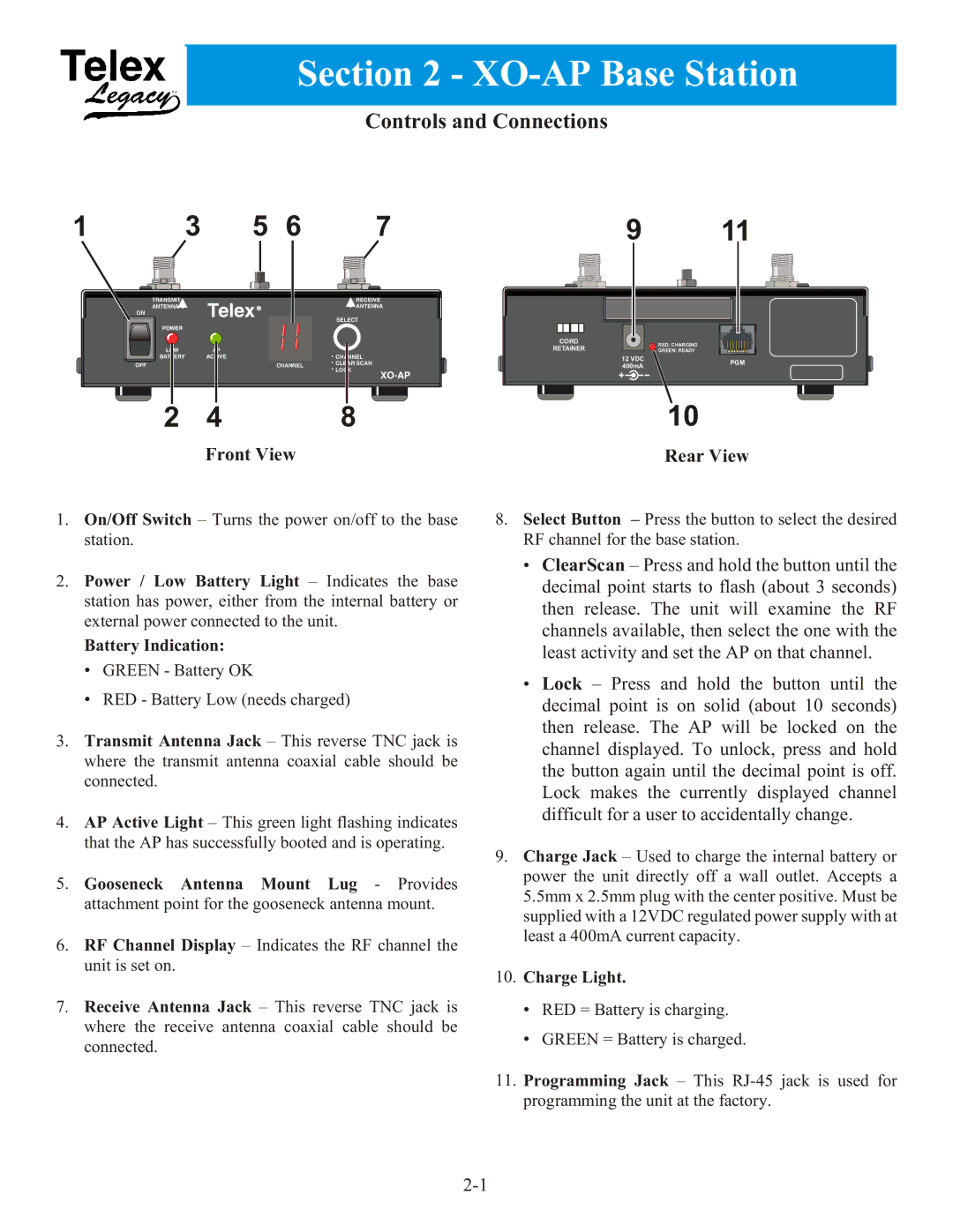
| Front View |
|
9 | 11 | |
CORD | RED: CHARGING | |
RETAINER | ||
GREEN: READY | ||
12 VDC | PGM | |
400mA | ||
| ||
| 10 |
Rear View
1. On/Off Switch – Turns the power on/off to the base | 8. Select Button – Press the button to select the desired |
station. | RF channel for the base station. |
2.Power / Low Battery Light – Indicates the base station has power, either from the internal battery or external power connected to the unit.
Battery Indication:
•GREEN - Battery OK
•RED - Battery Low (needs charged)
3.Transmit Antenna Jack – This reverse TNC jack is where the transmit antenna coaxial cable should be connected.
4.AP Active Light – This green light flashing indicates that the AP has successfully booted and is operating.
5.Gooseneck Antenna Mount Lug - Provides attachment point for the gooseneck antenna mount.
6.RF Channel Display – Indicates the RF channel the unit is set on.
7. Receive Antenna Jack – This reverse TNC jack is where the receive antenna coaxial cable should be connected.
•ClearScan – Press and hold the button until the decimal point starts to flash (about 3 seconds) then release. The unit will examine the RF channels available, then select the one with the least activity and set the AP on that channel.
•Lock – Press and hold the button until the decimal point is on solid (about 10 seconds) then release. The AP will be locked on the channel displayed. To unlock, press and hold the button again until the decimal point is off. Lock makes the currently displayed channel difficult for a user to accidentally change.
9.Charge Jack – Used to charge the internal battery or power the unit directly off a wall outlet. Accepts a 5.5mm x 2.5mm plug with the center positive. Must be supplied with a 12VDC regulated power supply with at least a 400mA current capacity.
10.Charge Light.
•RED = Battery is charging.
•GREEN = Battery is charged.
11.Programming Jack – This