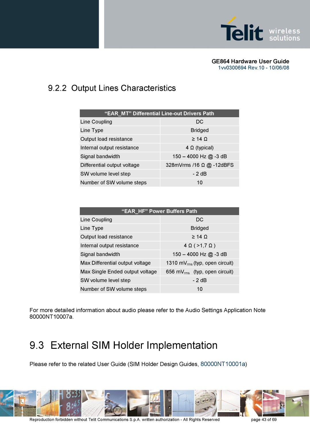
GE864 specifications
The Telit Wireless Solutions GE864 is a compact yet robust cellular module designed for a wide range of M2M (Machine-to-Machine) applications. As part of the Telit family, the GE864 is particularly notable for its small form factor, reliability, and versatility, making it an ideal choice for various industries including automotive, healthcare, and utilities.One of the standout features of the GE864 is its integrated GPRS capabilities, allowing devices to connect to cellular networks seamlessly. With a maximum data rate of 85.6 kbps for downlink and 42.8 kbps for uplink, this module facilitates efficient data transmission, suitable for applications that require real-time data monitoring and control.
The GE864 supports multiple frequency bands, ensuring global compatibility. It can operate on GSM/GPRS networks, enhancing its usability across different regions. This multi-band support allows developers to deploy their solutions in diverse markets without modifying the hardware, thus saving both time and resources.
Power management is another critical area where the GE864 shines. The module comes equipped with advanced power-saving features, allowing it to operate effectively in battery-powered applications. Notable features include sleep modes and intelligent power management protocols that help extend battery life while maintaining reliable connectivity.
In terms of physical specifications, the GE864 has a compact design, measuring only 29x38 mm, which is essential for integration into space-constrained environments. This makes it particularly well-suited for applications in remote monitoring, asset tracking, and utility metering.
The module supports a range of interfaces, including UART, USB, and I2C, providing developers with the flexibility to connect various peripheral devices and sensors. This versatility enables the creation of customized solutions tailored to specific application needs.
Furthermore, the GE864 is designed to meet rigorous quality and durability standards, making it suitable for use in harsh environments. Its resilience to extreme temperatures and vibrations ensures dependable performance in challenging conditions, which is often a requirement in industrial and automotive applications.
In summary, the Telit Wireless Solutions GE864 is a feature-rich cellular module that combines compact design with robust performance and versatility. Its advanced connectivity options, efficient power management, and reliable operation make it an invaluable asset for businesses looking to develop innovative M2M solutions. Whether it’s for smart cities, telematics, or healthcare applications, the GE864 is engineered to meet the demands of today's connected world.

