Background

1.1 Background

The bq2400x series ICs are advanced Li-Ion linear charge management devices for highly integrated and space-limited applications. They combine high-accuracy current and voltage regulation; FET pass-transistor and reverse-blocking Schottky; battery conditioning, temperature, or input-power monitoring; charge termination; charge-status indication; and charge timer in a small, 20-lead TSSOP PowerPAD package.

The bq2400x continuously measures battery temperature using an external thermistor. For safety reasons, the bq2400x inhibits charge until the battery temperature is within the user-defined thresholds. Alternatively, the user can monitor the input voltage to qualify charge. The bq2400x series then charge the battery in three phases: preconditioning, constant current and constant voltage. If the battery voltage is below the internal low-voltage threshold, the bq2400x uses trickle-charge to condition the battery. A preconditioning timer is provided for additional safety. Following preconditioning, the bq2400x applies a constant-charge current to the battery. An external sense-resistor sets the magnitude of the current. The constant-current phase is maintained until the battery reaches the charge-regulation voltage. The bq2400x then transitions to the constant voltage phase. The user can configure the device for cells with either coke or graphite anodes.

Charge is terminated by either of the following methods:

-Maximum time

-Minimum current detection

1.2Performance Specification Summary

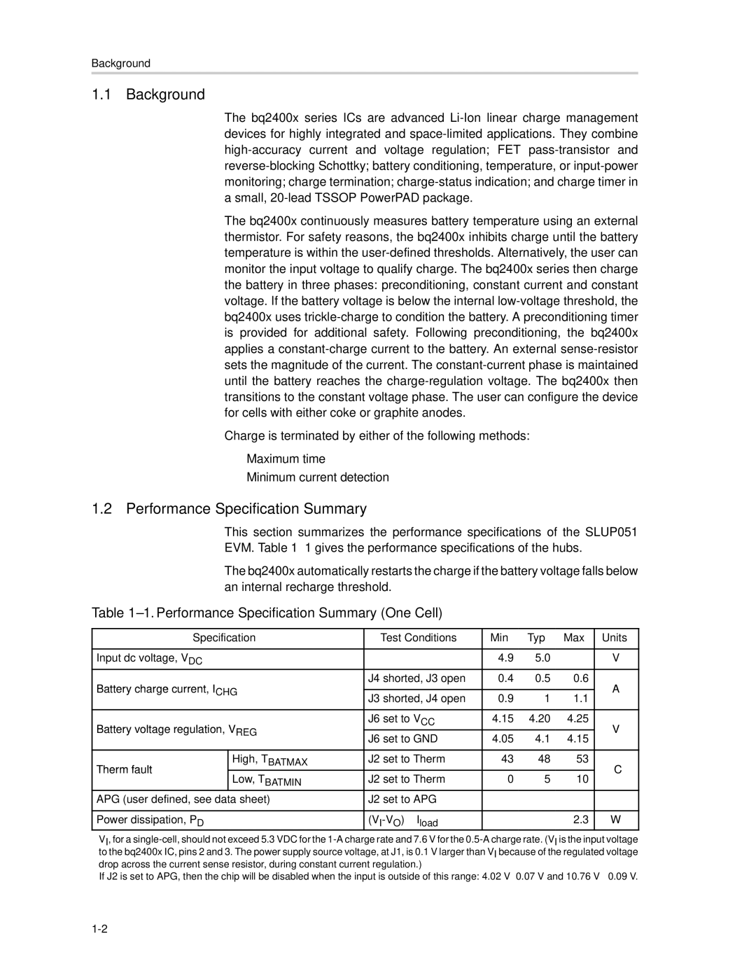
This section summarizes the performance specifications of the SLUP051 EVM. Table 1–1 gives the performance specifications of the hubs.

The bq2400x automatically restarts the charge if the battery voltage falls below an internal recharge threshold.

Table 1–1. Performance Specification Summary (One Cell)

Specification

Test Conditions

Min

Typ

Max

Units


Input dc voltage, VDC


4.9

5.0

V

Battery charge current, ICHG

J4 shorted, J3 open

0.4

0.5

0.6

A


J3 shorted, J4 open

0.9

1

1.1


Battery voltage regulation, VREG

J6 set to VCC

4.15

4.20

4.25

V

J6 set to GND

4.05

4.1

4.15


Therm fault

High, TBATMAX

J2 set to Therm

43

48

53

° C

Low, TBATMIN

J2 set to Therm

0

5

10


APG (user defined, see data sheet)

J2 set to APG


Power dissipation, PD

(VI-VO) × Iload


2.3

W

VI, for a single-cell, should not exceed 5.3 VDC for the 1-A charge rate and 7.6 V for the 0.5-A charge rate. (VI is the input voltage to the bq2400x IC, pins 2 and 3. The power supply source voltage, at J1, is 0.1 V larger than VI because of the regulated voltage drop across the current sense resistor, during constant current regulation.)

If J2 is set to APG, then the chip will be disabled when the input is outside of this range: 4.02 V± 0.07 V and 10.76 V ± 0.09 V.

1-2

Page 6
Image 6
Texas Instruments SLUU083A manual Background, Performance Specification Summary One Cell

SLUU083A specifications

Texas Instruments SLUU083A, technically known as the "Application Report: PFC Design With TL497," is a seminal document that provides comprehensive insights into the design and implementation of power factor correction (PFC) circuits using the TL497 PWM controller. This application report is crucial for engineers focused on enhancing power efficiency in various applications, particularly in consumer electronics and industrial equipment.

One of the main features of the SLUU083A report is its detailed exploration of power factor correction, which helps in reducing energy consumption and minimizing the impact of harmonic distortion on electrical systems. The document outlines PFC methodologies that comply with international standards and regulatory requirements, ensuring that designers can create products that meet strict energy efficiency regulations.

The report introduces the TL497 as a versatile PWM controller that plays a pivotal role in managing power conversion processes. This controller offers features like a wide input voltage range, making it suitable for various applications from 85V AC to 265V AC. It also incorporates a high degree of integration, which simplifies designs and minimizes the size of PFC circuits.

The application report covers technologies such as continuous conduction mode (CCM) and discontinuous conduction mode (DCM), showcasing the advantages and trade-offs of each mode. Using CCM enhances efficiency under heavy loads, whereas DCM results in reduced power losses at light loads, presenting designers with options tailored to their specific requirements.

Another noteworthy characteristic of the SLUU083A report is its emphasis on component selection and layout guidelines that optimize performance and reliability. The report provides helpful calculations and design examples, illustrating how to achieve a desired output voltage and minimize losses.

In conclusion, Texas Instruments SLUU083A serves as an essential resource for engineers designing PFC circuits with the TL497 PWM controller. Its emphasis on efficiency, regulatory compliance, and practical design considerations makes it a valuable reference in the field of power management. The integration of innovative technologies and robust guidelines ensures that designers can create systems that not only comply with regulations but also provide reliable and effective power conversion. This combination of features and characteristics establishes SLUU083A as a go-to document for advancing power efficiency solutions in diverse applications.