TNETE2201 specifications
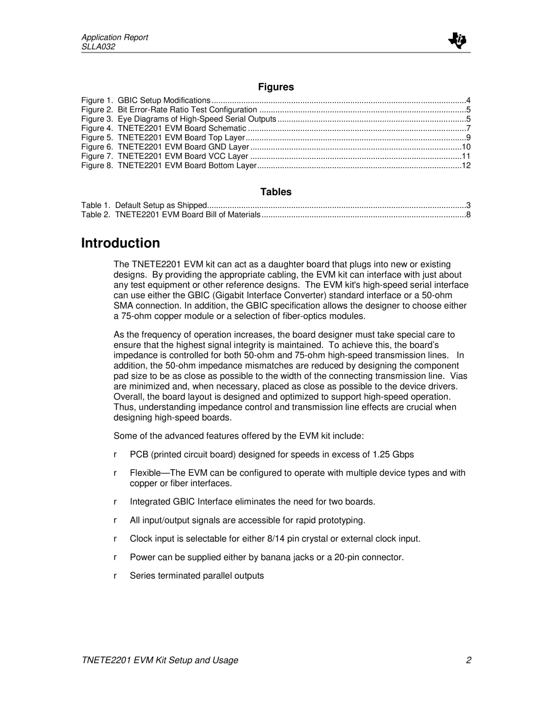
Texas Instruments TNETE2201 is a highly integrated, versatile chip designed for embedded networking applications. Operating in the realm of Ethernet connectivity, this device serves as a robust solution for various communication needs, especially within industrial and automotive sectors. Its key features and innovative technologies position it as a reliable choice for manufacturers looking to enhance their products' networking capabilities.One of the standout attributes of the TNETE2201 is its support for multiple Ethernet protocols, enabling seamless integration into a variety of communication systems. The device is compliant with IEEE 802.3 standards, ensuring compatibility and reliability across different networking platforms. This compliance allows for easy integration into existing infrastructures while maintaining high-speed communication standards.
The TNETE2201 is equipped with an integrated Media Access Controller (MAC) that simplifies the design process by reducing the need for external components. This feature results in a more compact and efficient design, reducing overall system costs and enhancing performance. The MAC interface supports various data rates, including 10/100 Mbps operation, making it suitable for both legacy and modern networking applications.
Another significant characteristic of the TNETE2201 is its low power consumption, which is crucial for portable and battery-operated devices. The chip operates in power-saving modes, ensuring operational efficiency without compromising performance. This attribute is particularly valuable in applications where energy efficiency is critical, such as remote sensors and IoT devices.
Additionally, the TNETE2201 supports advanced packet processing capabilities, including the ability to handle multiple data streams, which is essential for applications requiring real-time data transmission. Its built-in features for Quality of Service (QoS) allow for prioritization of critical data, thus facilitating better management of network traffic.
The device also integrates various safety and security measures, essential for today’s interconnected environments. With features designed to prevent unauthorized access and secure data transmission, the TNETE2201 aligns with industry standards for cybersecurity, making it a dependable component for any secure networking application.
Overall, Texas Instruments’ TNETE2201 stands out due to its blend of high performance, low power consumption, and extensive compatibility across various platforms. Its advanced integration capabilities and robust networking features make it an invaluable asset for designers aiming to develop innovative and reliable networking solutions in today's rapidly evolving technological landscape. Whether for industrial automation, automotive networking, or IoT applications, the TNETE2201 positions itself as a top choice for manufacturers looking to leverage Ethernet technology.
