Using The TPA0103 EVM With the
3.3.2TPA0103 Module Jumper Settings
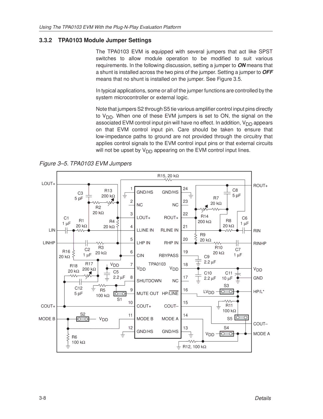
The TPA0103 EVM is equipped with several jumpers that act like SPST switches to allow module operation to be modified to suit various requirements. In the following discussion, setting a jumper to ON means that a shunt is installed across the two pins of the jumper. Setting a jumper to OFF means that no shunt is installed on the jumper. See Figure 3.5.
In typical applications, some or all of the jumper functions are controlled by the system microcontroller or external logic.
Note that jumpers S2 through S5 tie various amplifier control input pins directly to VDD. When one of these EVM jumpers is set to ON, the signal on the associated EVM control input pin will have no effect. In addition, VDD appears on that EVM control input pin. Care should be taken to ensure that
Figure 3±5. TPA0103 EVM Jumpers
|
|
|
|
|
| R15, 20 kΩ |
|
|
|
|
|
| ||
LOUT+ |
|
|
|
|
|
|
|
|
|
|
|
|
| ROUT+ |
|
|
|
|
| 1 |
|
| 24 |
|
| C8 |
| ||
|
|
|
| R13 |
|
|
|
|
|
| ||||
| C3 |
|
| GND/HS | GND/HS |
|
|
|
| |||||
|
| 200 kΩ |
|
|
| 5 pF |
| |||||||
| 5 pF |
|
|
|
|
|
| R7 |
| |||||
|
|
| 2 |
|
| 23 |
|
|
|
|
| |||
|
|
|
|
|
|
|
| 20 kΩ |
|
|
|
| ||
|
|
|
| R2 |
| NC |
| NC |
|
|
|
|
| |
|
|
|
|
|
|
|
|
|
|
|
| |||
|
|
|
|
|
|
|
|
|
|
|
|
|
| |
|
|
| 20 kΩ | 3 |
|
| 22 | R14 |
|
|
|
|
| |
C1 | R1 |
|
| LOUT+ | ROUT+ |
| R8 |
| C6 | |||||
R4 |
| 200 kΩ |
| |||||||||||
1 μF |
|
|
|
|
| 1 | μF | |||||||
20 kΩ | 20 kΩ | 4 |
|
| 21 |
|
| 20 kΩ | ||||||
LIN |
|
|
|
|
|
| ||||||||
|
|
|
|
| LLINE IN | RLINE IN | R9 |
|
|
|
| RIN | ||
|
|
|
|
| 5 |
|
| 20 |
|
|
|
|
| |
LINHP |
|
|
|
| LHP IN |
| 20 kΩ |
|
|
| RINHP | |||
|
|
| R3 |
| RHP IN |
| R10 |
|
| |||||
R16 |
|
| C2 | 6 |
|
| 19 |
| C7 |
| ||||
|
| 20 kΩ |
|
|
| 20 kΩ |
| |||||||
|
| 1 μF |
|
|
| 1 μF |
| |||||||
20 kΩ |
|
|
| CIN | RBYPASS | C9 |
| |||||||
R18 |
| R17 | VDD | 7 | TPA0103 | 18 | 2.2 μF |
|
|
|
| |||
|
|
|
|
|
|
| ||||||||
|
| 200 kΩ |
| VDD |
| VDD |
|
|
|
|
| V | ||
20 kΩ |
|
| C5 |
|
|
|
| C10 | C11 |
|
| DD | ||
|
|
|
| 2.2 μF | 8 | SHUTDOWN | 17 | 2.2 μF | 10 μF |
|
| GND | ||
|
|
|
|
|
| NC |
|
| S3 |
|
|
| ||
| C12 |
| R5 | 9 |
|
| 16 |
|
|
|
|
| ||
|
|
|
| LVDD |
|
|
| HP/L* | ||||||
| 5 pF |
| MUTE OUT |
|
|
|
| |||||||
|
| 100 kΩ |
| HP/LINE |
|
|
| |||||||
|
|
|
| S1 | 10 |
|
| 15 |
|
|
|
|
|
|
COUT+ |
|
|
|
| COUT+ |
|
|
| R11 |
|
|
| ||
|
|
|
|
| COUT± |
|
|
|
|
| ||||
|
| S2 |
| 11 |
|
| 14 |
|
| 100 kΩ |
|
| ||
MODE B |
| VDD |
|
|
|
| S5 |
|
|
| ||||
|
|
|
| MODE B | MODE A |
|
|
|
| COUT± | ||||
|
|
|
|
| 12 |
|
| 13 |
|
| S4 |
|
| |
|
|
|
|
| GND/HS |
|
|
|
|
|
| |||
|
|
|
|
|
| GND/HS | VDD |
|
|
| MODE A | |||
| R6 |
|
|
|
|
|
|
|
|
|
| |||
|
|
|
|
|
|
|
|
|
|
|
|
|
| |
| 100 kΩ |
|
|
|
| R12, 100 kΩ |
|
|
|
|
| |||
|
|
|
|
|
|
|
|
|
|
|
|
| ||
|
|
|
|
|
|
|
|
|
|
|
|
| Details | |