Jumper Settings
This section explains how to set jumpers for correct configuration of the mainboard.
Setting Jumpers
Use the motherboard jumpers to set system configuration options. Jumpers with more than one pin are numbered. When setting the jumpers, ensure that the jumper caps are placed on the correct pins.
System Board Jumper Setting
Features | Default setting | Remark (color and | ||
| other) | |||
|
|
|
| |
|
|
|
|
|
CLR_CMOS(PIN2_3)1 | : Clear CMOS | |||
default setting (See Pin | & default setting |
| : Normal (Default) | |
definition for the detail) |
|
|
|
|
|
|
|
| |
|
|
|
|
|
|
|
|
|
|
|
|
|
|
|
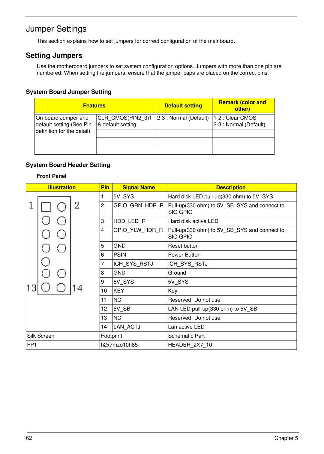
System Board Header Setting
Front Panel
Illustration | Pin | Signal Name | Description |
|
|
|
|
| 1 | 5V_SYS | Hard disk LED |
|
|
|
|
| 2 | GPIO_GRN_HDR_R | |
|
|
| SIO GPIO |
|
|
|
|
| 3 | HDD_LED_R | Hard disk active LED |
|
|
|
|
| 4 | GPIO_YLW_HDR_R | |
|
|
| SIO GPIO |
|
|
|
|
| 5 | GND | Reset button |
|
|
|
|
| 6 | PSIN | Power Button |
|
|
|
|
| 7 | ICH_SYS_RSTJ | ICH_SYS_RSTJ |
|
|
|
|
| 8 | GND | Ground |
|
|
|
|
| 9 | 5V_SYS | 5V_SYS |
|
|
|
|
| 10 | KEY | Key |
|
|
|
|
| 11 | NC | Reserved. Do not use |
|
|
|
|
| 12 | 5V_SB | LAN LED |
|
|
|
|
| 13 | NC | Reserved. Do not use |
|
|
|
|
| 14 | LAN_ACTJ | Lan active LED |
|
|
|
|
Silk Screen | Footprint | Schematic Part | |
|
|
| |
FP1 | h2x7mzo10h85 | HEADER_2X7_10 | |
|
|
|
|
62 | Chapter 5 |