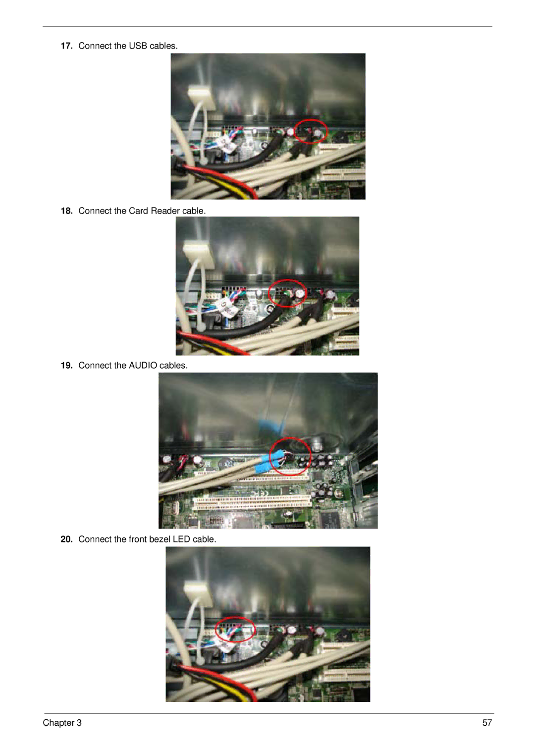
Manuals
/
Aspire Digital
/
Computer Equipment
/
Computer Hardware
Aspire Digital
M261, M1610 manual Connect the USB cables 18. Connect the Card Reader cable, Chapter
Models:
M261
M1610
1
65
80
80
Download
80 pages
33.8 Kb
62
63
64
65
66
67
68
69
<
>
Troubleshooting
Specifications
Install
Parts list
Block Diagram
Mainboard Placement
PnP/PCI Configuration
Entering Setup
Disassembly Procedure
LAN - Realtek8211BLdefault co-lay 8201CL phy
Page 65
Image 65
17.
Connect the USB cables.
18.
Connect the Card Reader cable.
19.
Connect the AUDIO cables.
20.
Connect the front bezel LED cable.
Chapter 3
57
Page 64
Page 66
Page 65
Image 65
Page 64
Page 66
Contents
PRINTED IN TAIWAN
Service Guide
Aspire M1610/Veriton M261
Revision History
Disclaimer
Copyright
MESSAGES
Conventions
SCREEN
Preface
Page
System Specifications
Table of Contents
Entering Setup Product Information Standard CMOS Features
Advanced BIOS Features CPU Feature Hard Disk Boot Priority
Troubleshooting
Machine Disassembly and Replacement
Jumper and Connector Information
General Information Before You Begin Disassembly Procedure
Features
System Specifications
Chapter
Operating System
IEEE 1394 Reserved
BIOS
Audio
Rear I/O Connector
I/O Connector
Onboard Connector
Power Supply
Chapter
Mainboard Placement
Chapter
Block Diagram
The computer’s front panel consists of the following
Aspire M1610 Front Panel
Aspire M1610 Rear Panel
The computer’s front panel consists of the following
Veriton M261 Front Panel
Chapter
Veriton M261 Rear Panel
The computer’s rear panel consists of the following
Processor Support
Hardware Specifications and Configurations
System Memory Interface
System Clock
Audio Sub-Systems - Realtek ALC888SCo-lay ALC888
SiS 968 MuTIOL 1G Media I/O
Super I/O - IT8718F
Universal Serial Bus
LAN - Realtek8211BLdefault co-lay 8201CL phy
TSB43AB23PDTG4 Host Controller
Expansion Slots
Hardware Monitor Function
Power & Power Management
Wake-Up Event
From ACPI State
LPC Bus
System BIOS
SPI Bus default
Chapter
System Utilities
Entering Setup
Exit Without Saving - Abandon all CMOS value changes and exit setup
Save & Exit Setup - Save CMOS value settings to CMOS and exit setup
The items in the main menu are explained below
PC Health Status - This will display the current status of your PC
Product Information
Base Memory
Standard CMOS Features
640K
Extended Memory
Description
Parameter
Options
1.44M, 3.5 - inch
IDE Channel 0/1 Master
The following screen shows the IDE Channel Slave menu
IDE Channel 0/1 Slave
SATA Channel 1/2 Master
X Typematic Rate chars/sec
Advanced BIOS Features
X Typematic Delay Msec
Setting to Off will allows users to use the arrow
NOTE Change these settings only if you are familiar with the chipset
password prompt appears only when end users
try to run Setup. System means that a password
The following screen shows the CPU Features menu
CPU Feature
Hard Disk Boot Priority
The following screen shows the Advanced Chipset Features menu
Advanced Chipset Features
X VGA Share Memory Size
Internal Graphic Control
256 MB
Graphic Engine Clock
The following screen shows the Integrated Peripherals Features
Integrated Peripherals
Onboard IDE Device
The following screen shows the Onboard PCI Device menu
Onboard PCI Device
Half
Onboard Super IO Device
X UR2 Duplex Mode
X Month Alarm
Power Management
X Day of Month Alarm
X Time hh mm ss Alarm
connect the AC power. Always off means the machine is
using an ATX power supply. When ““instant off” is selected
machine will always power on when connect the AC power
Chapter
PCI Express relative items
PnP/PCI Configuration
PC Health Status
pulses are reduced to flatter curves. If you do not
Frequency/Voltage Control
the extreme values spikes of the pulses creates
Load Optimized Defaults
Set Supervisor/User Password
Save & Exit Setup
Exit Without Saving
Chapter
Machine Disassembly and Replacement
Before You Begin
General Information
Aspire M1610/Veriton M261 Disassembly
Disassembly Procedure
5. Disconnect the audio cables 6. Disconnect the USB cable
4. Disconnect the front bezel LED cable
7. Disconnect the Card Reader cable
Chapter
9. Disconnect P1 power cable and FDD data cable
8. Disconnect the PA and PD power-cable from the MB connector
10. Disconnect the ODD power and data cables
Chapter
Chapter
11. Disconnect the HDD power and data cables
12. Disconnect the System Fan power-cable from the MB connector
Front Bezel
Front Bezel
Chapter
Aspire M1610
Chapter
17. Disconnect the CPU Cooler power-cable from the MB connector
18. Release the memory
Chapter
Aspire M1610/Veriton M261 Reassembly
Reassembly Procedure
Chapter
5. Install the Memory
6. Fit the CPU cooler to the MB and fasten four screws shown
8. Connect the System Fan power-cable to the MB connector
7. Connect the CPU Cooler power-cable to the MB connector
9. Install the ODD into the chassis and slide the ODD rail to lock it
10. Install the FDD and slide the FDD rail to lock it
13. Connect the HDD data cable and power-cable to the rear of HDD
11. Install the front bezel
Veriton M261
Front Bezel
15. Connect the P1 power-cable and FDD data cable to the MB connector
14. Connect the ODD data cable and power-cable to the rear of ODD
16. Connect the PA and PD power-cable to the MB connector
Chapter
Chapter
17. Connect the USB cables 18. Connect the Card Reader cable
19. Connect the AUDIO cables 20. Connect the front bezel LED cable
Chapter
21. Install the TV&VGA&MODEM card 22. Close the system
Chapter
Troubleshooting
Chapter
Chapter
Jumper and Connector Information
Mainboard Jumper Locations
Setting Jumpers
Jumper Settings
System Board Jumper Setting
System Board Header Setting
Front Audio
Sys FAN 3pin
Front
HFAN4MM1
CPU FAN 4pin
CONN3FAN4P
Clear CMOS
HEADER1X2
COM2
Chapter
Chapter
FRU Field Replaceable Unit List
Aspire M1610
Exploded Diagrams
Chapter
Veriton M261
The SPL will update later
Parts Lists