Connector and Test Point Descriptions | www.ti.com |
4 Connector and Test Point Descriptions
4.1Enable Jumpers/Switches –SW1 and SW2
The TPS53125EVM-599 board includes independent enable switches for each of the two outputs. When the switch is in the DIS position, the channel is disabled and discharged per the TPS53125’s internal discharge characteristics.
To enable VOUT1, place SW1 in the EN position. To enable VOUT2, place SW2 in the EN position.
4.2Test Point Descriptions
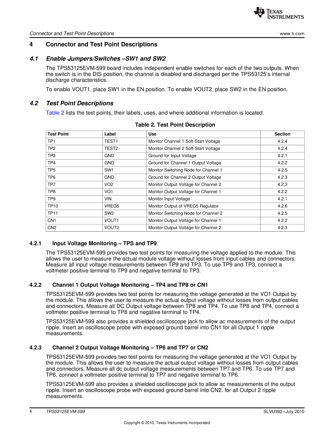
Table 2 lists the test points, their labels, uses, and where additional information is located.
Table 2. Test Point Description
Test Point | Label | Use | Section |
| | | |
TP1 | TEST1 | Monitor Channel 1 Soft-Start Voltage | 4.2.4 |
| | | |
TP2 | TEST2 | Monitor Channel 2 Soft-Start Voltage | 4.2.4 |
| | | |
TP3 | GND | Ground for Input Voltage | 4.2.1 |
| | | |
TP4 | GND | Ground for Channel 1 Output Voltage | 4.2.2 |
| | | |
TP5 | SW1 | Monitor Switching Node for Channel 1 | 4.2.5 |
| | | |
TP6 | GND | Ground for Channel 2 Output Voltage | 4.2.3 |
| | | |
TP7 | VO2 | Monitor Output Voltage for Channel 2 | 4.2.3 |
| | | |
TP8 | VO1 | Monitor Output Voltage for Channel 1 | 4.2.2 |
| | | |
TP9 | VIN | Monitor Input Voltage | 4.2.1 |
| | | |
TP10 | VREG5 | Monitor Output of VREG5 Regulator | 4.2.6 |
| | | |
TP11 | SW2 | Monitor Switching Node for Channel 2 | 4.2.5 |
| | | |
CN1 | VOUT1 | Monitor Output Voltage for Channel 1 | 4.2.2 |
| | | |
CN2 | VOUT2 | Monitor Output Voltage for Channel 2 | 4.2.3 |
| | | |
4.2.1Input Voltage Monitoring – TPS and TP9
The TPS53125EVM-599 provides two test points for measuring the voltage applied to the module. This allows the user to measure the actual module voltage without losses from input cables and connectors. Measure all input voltage measurements between TP9 and TP3. To use TP9 and TP3, connect a voltmeter positive terminal to TP9 and negative terminal to TP3.
4.2.2Channel 1 Output Voltage Monitoring – TP4 and TP8 or CN1
TPS53125EVM-599 provides two test points for measuring the voltage generated at the VO1 Output by the module. This allows the user to measure the actual output voltage without losses from output cables and connectors. Measure all DC Output voltage between TP8 and TP4. To use TP8 and TP4, connect a voltmeter positive terminal to TP8 and negative terminal to TP4.
TPS53125EVM-599 also provides a shielded oscilloscope jack to allow ac measurements of the output ripple. Insert an oscilloscope probe with exposed ground barrel into CN1 for all Output 1 ripple measurements.
4.2.3Channel 2 Output Voltage Monitoring – TP6 and TP7 or CN2
TPS53125EVM-599 provides two test points for measuring the voltage generated at the VO1 Output by the module. This allows the user to measure the actual output voltage without losses from output cables and connectors. Measure all dc output voltage measurements between TP7 and TP6. To use TP7 and TP6, connect a voltmeter positive terminal to TP7 and negative terminal to TP6.
TPS53125EVM-599 also provides a shielded oscilloscope jack to allow ac measurements of the output ripple. Insert an oscilloscope probe with exposed ground barrel into CN2. for all Output 2 ripple measurements.
4 | TPS53125EVM-599 | SLVU392 –July 2010 |
Copyright © 2010, Texas Instruments Incorporated