www.ti.com | Test Setup |
5.2.2Test Setup Diagram
FAN
|
|
|
| Oscilloscope |
| |
+ |
| - |
| 1MΩ, AC |
| |
V1 |
| 20mV / div |
| |||
|
|
| 20MHz |
| ||
|
|
|
|
| ||
|
|
|
| + LOAD1 | + | |
|
|
|
|
| 1.05V @ | V2 |
|
|
|
| - | 4A | |
|
|
|
| - | ||
|
|
|
|
|
| |
|
|
|
| - | LOAD2 | - |
|
|
|
|
| ||
|
|
|
|
| 1.8V @ | V3 |
|
|
|
|
|
| |
|
|
|
| + | 4A | + |
|
|
|
|
| ||
|
|
|
|
|
| |
|
|
| A1 | + |
|
|
|
|
|
|
|
| |
|
|
|
| VVIN |
|
|
|
|
|
| - |
|
|
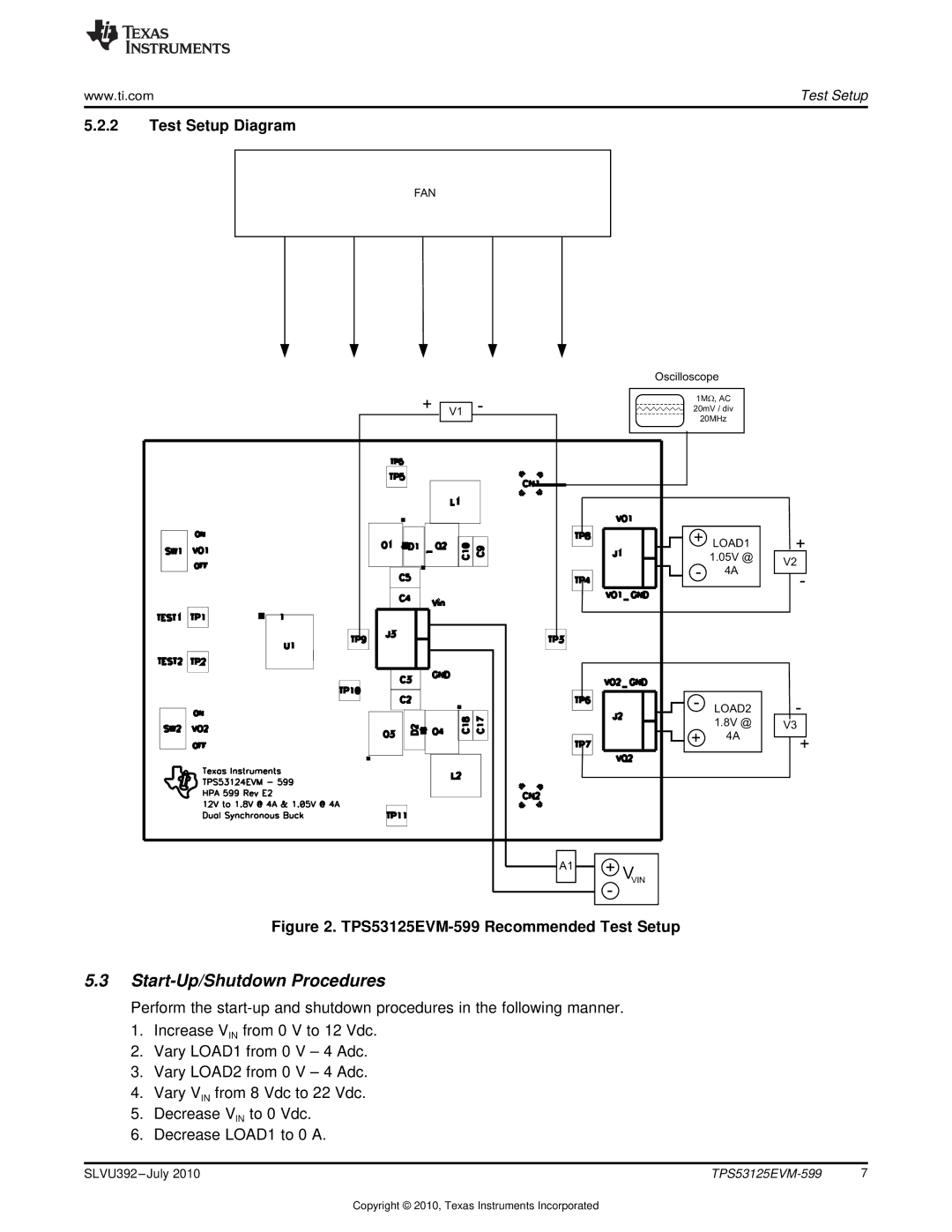
Figure 2. TPS53125EVM-599 Recommended Test Setup
5.3Start-Up/Shutdown Procedures
Perform the
1.Increase VIN from 0 V to 12 Vdc.
2.Vary LOAD1 from 0 V – 4 Adc.
3.Vary LOAD2 from 0 V – 4 Adc.
4.Vary VIN from 8 Vdc to 22 Vdc.
5.Decrease VIN to 0 Vdc.
6.Decrease LOAD1 to 0 A.
SLVU392 | 7 |
Copyright © 2010, Texas Instruments Incorporated