www.ti.com
EVM Test Setup
High efficiency is achieved using self-driven synchronous rectification on the secondary side. Q3 and Q4 are placed in parallel and make up the forward synchronous rectifier (SR), while the reverse SR is made up of the parallel combination of Q5, Q7 and Q8. If the duty cycle were limited to 50% then the reverse SR could be reduced to only two parallel MOSFETs, but since these devices are operating near 60% duty cycle during the freewheel mode, they carry a higher average current than seen by Q3 and Q4. The output inductor L1 has a coupled secondary, referenced to the primary side, used to provide bootstrapping voltage to U1. A stable bias for the optocoupler, U2 is provided by the series pass regulator made up of D6, Q6 and some associated filtering.
Scope jacks J2 and J3 allow the user to measure the gate-to-source and drain-to-source signals for Q2, the primary MOSFET. J4 and J5 allow convenient access to the gate drive signals of each SR on the secondary side. J6 and J7 are available allowing the option of using a network analyzer to non-invasively measure the control to output loop gain and phase.
5EVM Test Setup
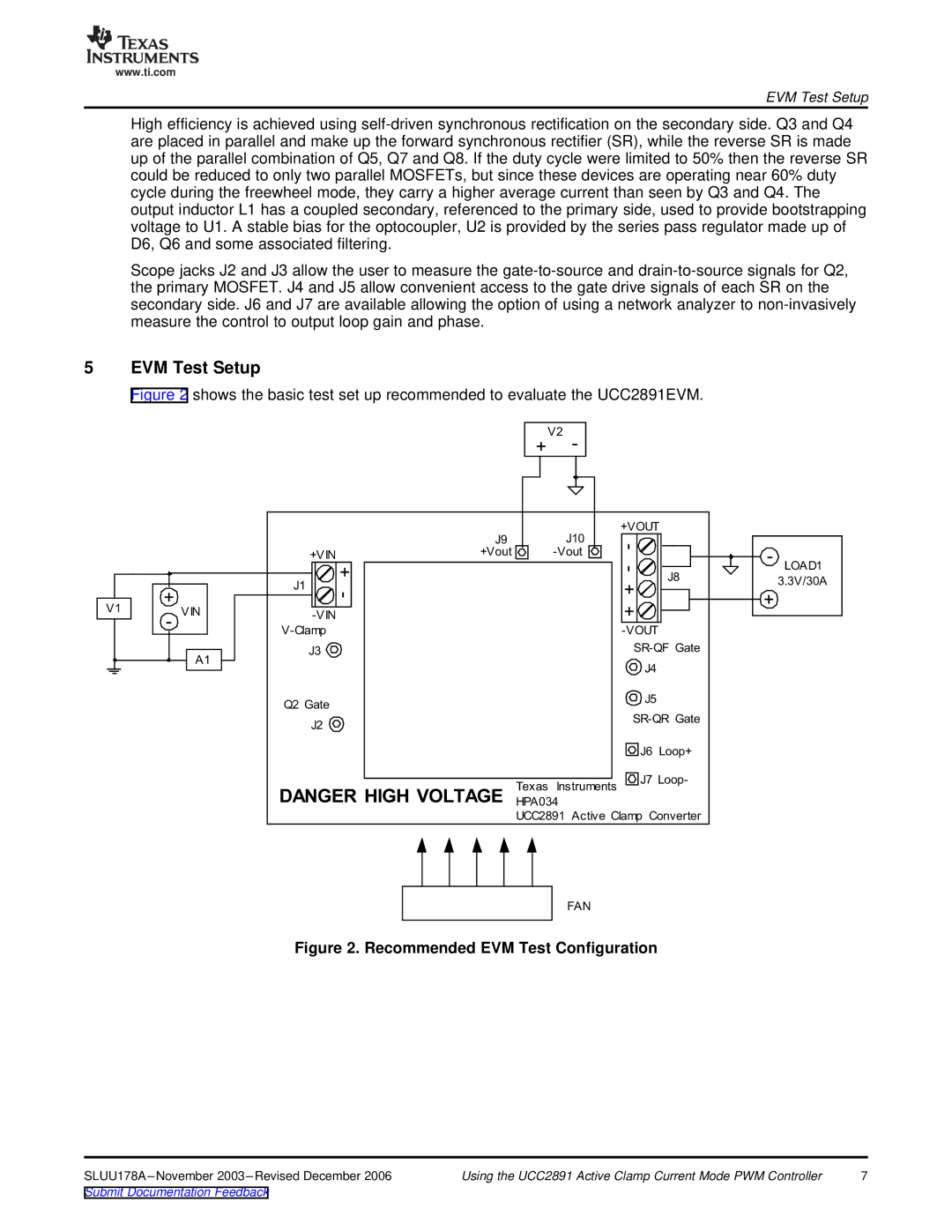
Figure 2 shows the basic test set up recommended to evaluate the UCC2891EVM.
| | | | | | V2 | |
| | | | | + | - | |
| | | | | | | +VOUT |
| | | | J9 | | J10 | - |
| | | | +Vout | | -Vout |
| | | +VIN | | |
| | | | | | |
| | | | + | | | - |
| | | J1 | | | | J8 |
| + | | - | | | + |
| | | | |
V1 | VIN | | | | | + |
- | -VIN | | | |
| | | | | |
| | V-Clamp | | | | -VOUT |
| | | | | |
| | | J3 | | | | SR-QF Gate |
| | A1 | | | | |
| | | | | | J4 |
| | | | | | |
| | | Q2 Gate | | | | J5 |
| | | | | | |
| | | J2 | | | | SR-QR Gate |
| | | | | | |
| | | | | | | J6 Loop+ |
| | | | | Texas Instruments | J7 Loop- |
| | | DANGER HIGH VOLTAGE | |
| | | HPA034 | |
| | | | | |
| | | | | UCC2891 Active Clamp Converter |
| | | | | | FAN | |
Figure 2. Recommended EVM Test Configuration
SLUU178A –November 2003 –Revised December 2006 | Using the UCC2891 Active Clamp Current Mode PWM Controller | 7 |
Submit Documentation Feedback