www.ti.com
EVM Assembly Drawing and Layout
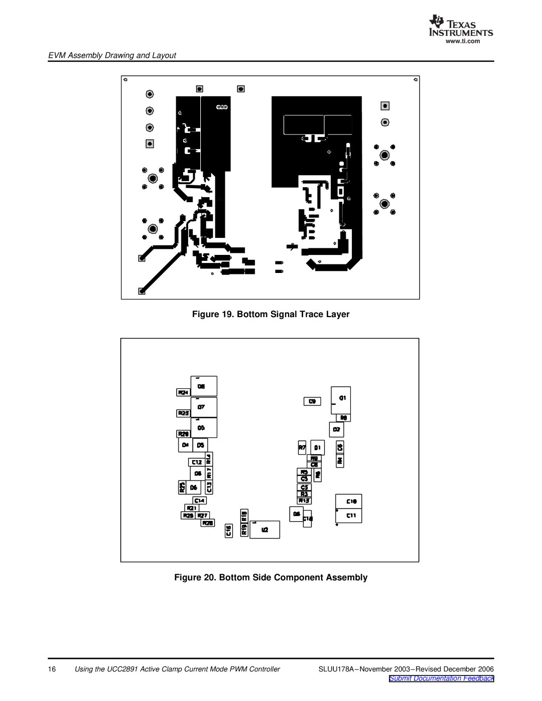
Figure 19. Bottom Signal Trace Layer
Figure 20. Bottom Side Component Assembly
16 | Using the UCC2891 Active Clamp Current Mode PWM Controller | SLUU178A |
Submit Documentation Feedback
www.ti.com
EVM Assembly Drawing and Layout
16 | Using the UCC2891 Active Clamp Current Mode PWM Controller | SLUU178A |
Submit Documentation Feedback