TTP-248M Bar Code Printer
Service Manual
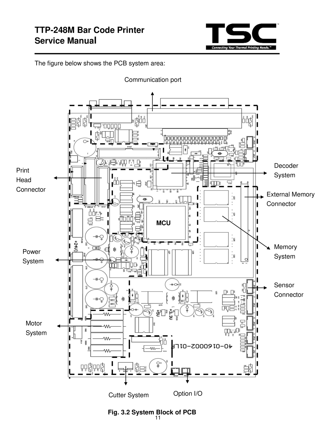
The figure below shows the PCB system area:
Communication port
Decoder | ||
System | ||
Head | ||
| ||
Connector | External Memory | |
| ||
| Connector | |
| MCU | |
Power | Memory | |
System | ||
System | ||
| ||
| Sensor | |
| Connector |
Motor
System
|
| Option I/O |
Cutter System |
| |
|
|
|
|
|
|
Fig. 3.2 System Block of PCB
11
