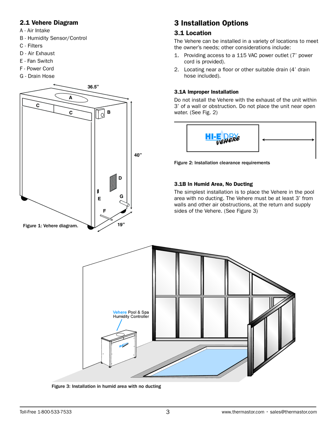
2.1 Vehere Diagram
A - Air Intake
B - Humidity Sensor/Control
C - Filters
D - Air Exhaust
E - Fan Switch
F - Power Cord
G - Drain Hose
36.5”
A
3 Installation Options
3.1 Location
The Vehere can be installed in a variety of locations to meet the owner’s needs; other considerations include:
1.Providing access to a 115 VAC power outlet (7’ power cord is provided).
2.Locating near a floor or other suitable drain (4’ drain hose included).
3.1A Improper Installation
Do not install the Vehere with the exhaust of the unit within
C
C
Figure 1: Vehere diagram.
![]() B
B
D
EG
F ![]()
19”
3’ of a wall or obstruction. Do not place the unit near open water. (See Fig. 2)
40”
Figure 2: Installation clearance requirements
3.1B In Humid Area, No Ducting
The simplest installation is to place the Vehere in the pool area with no ducting. The Vehere must be at least 3’ from walls and other air obstructions, at the return and supply sides of the Vehere. (See Figure 3)
Vehere Pool & Spa
Humidity Controller
Figure 3: Installation in humid area with no ducting
| www.thermastor.com • sales@thermastor.com |