Cabinet Installation: (Figure 5)
Note: distances on page 10, Table 3.
1.Find the centerline of the cabinet bottom. Draw a line along this centerline from rear to front of the cabinet.
2.Draw two lines, one at a K distance from the wall, the other one at a Z distance from the previous line.
Mark 4 points , two along each line at a distance of half W from the center line, to determine the screw locations.
3.Fit 4 screws on cabinet bottom do not tighten completely but leave a space of about 1/2” from cabinet bottom surface and head screws.
4.Run 8” Duct, long enough to reach the transition once the hood has been installed plus 1 1/2” inch for connect ductwork.
Fix Duct to transition with screws and seal with tape.
5.If mounted, remove the grease filter.
6.Remove 1 of 2 knockouts and install 1/2” conduit connector in
7.Hang the hood on screws through side slots provided on hood top.
Tighten the four screws.
If possible fix the hood on the wall at 4 additional point (2 on upper side, 2 on lower side).
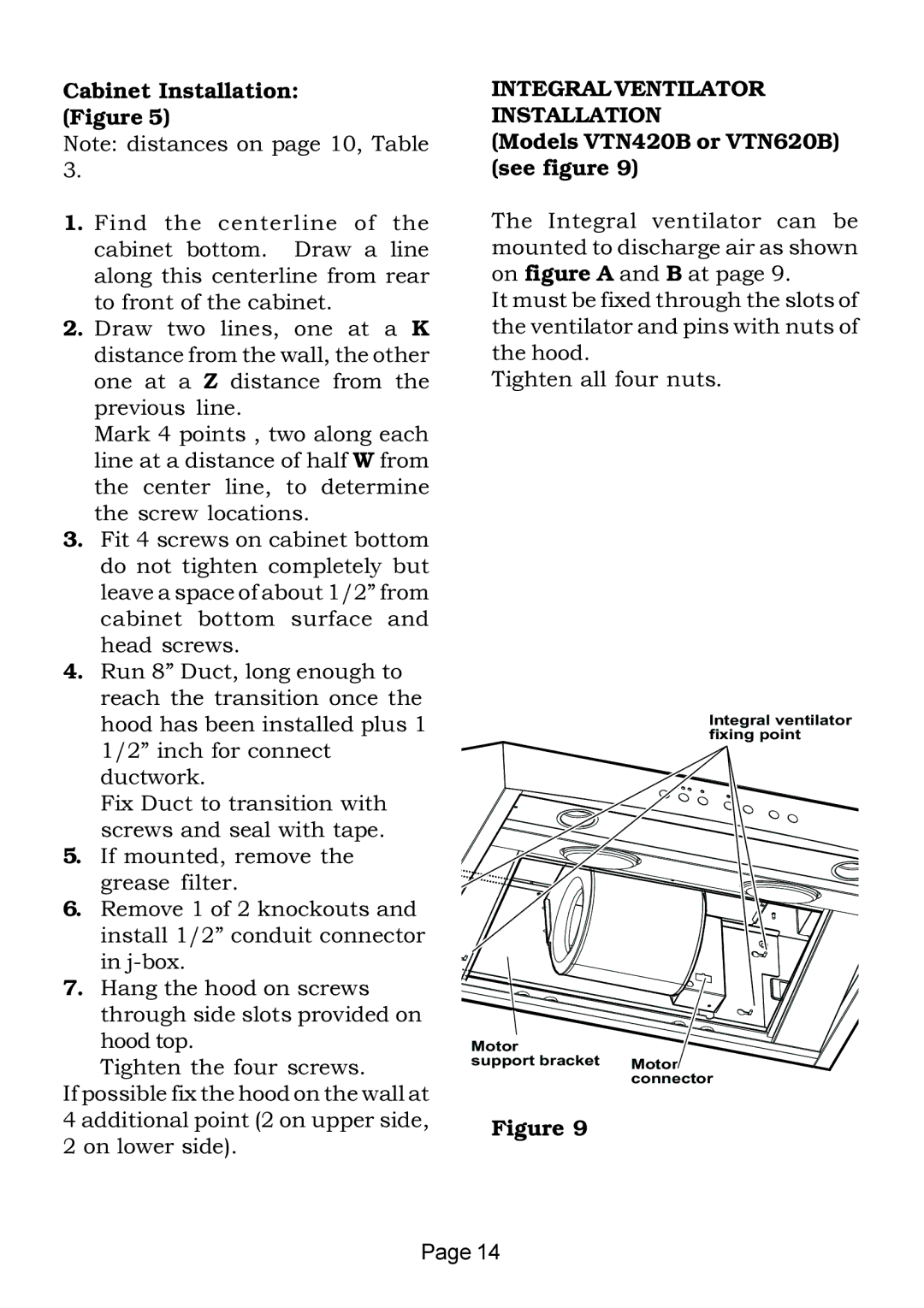
INTEGRAL VENTILATOR INSTALLATION
(Models VTN420B or VTN620B) (see figure 9)
The Integral ventilator can be mounted to discharge air as shown on figure A and B at page 9.
It must be fixed through the slots of the ventilator and pins with nuts of the hood.
Tighten all four nuts.
Integral ventilator fixing point
Motor
support bracket Motor connector
Figure 9
Page 14