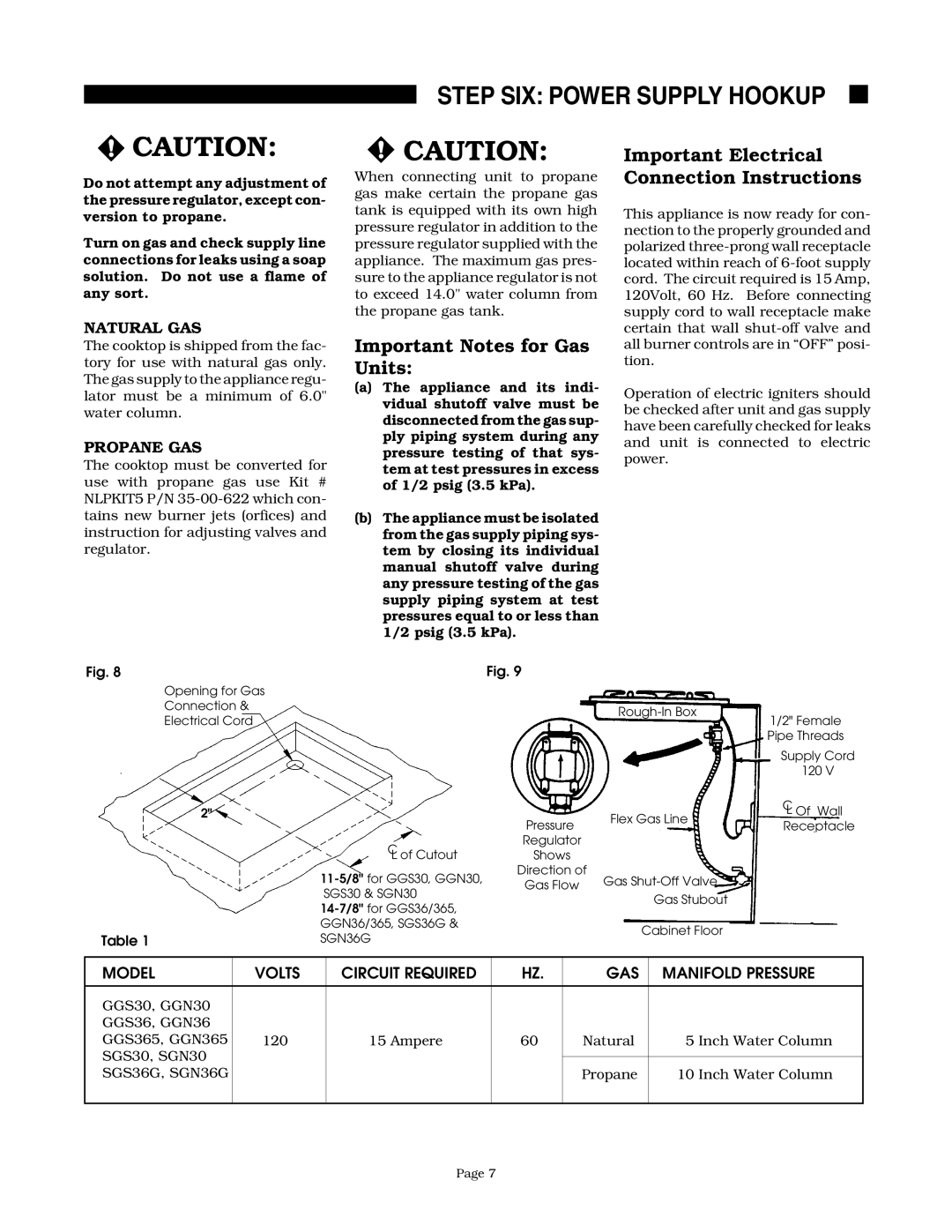
GGS365, GGS30, GGN365, GGN30, GGN36 specifications
The Thermador SGNCV36G, SGN36G, SGN30, GGNCV30, and GGNCV36 are part of Thermador’s premier collection of gas ranges, designed for culinary enthusiasts who prioritize performance, style, and technology in their kitchen. These models illustrate Thermador's dedication to professional-grade equipment, integrating robust features and advanced technologies that cater to both home chefs and culinary artisans.One of the standout characteristics of these ranges is their powerful heating elements. Each model is equipped with Thermador’s signature Star Burner design, which delivers superior heat distribution for even cooking results. With an impressive output ranging from 18,000 BTU for quick boiling to low simmer settings, users can easily navigate a wide array of cooking techniques, whether searing meats or delicate sauce preparation.
In addition to exceptional heating capabilities, the Thermador SGNCV36G and the GGNCV36 feature a seamless surface design that not only enhances aesthetic appeal but also simplifies cleaning. This innovative design minimizes gaps and crevices where food particles can accumulate, making maintenance a breeze. Moreover, the ranges come with continuous grates, allowing for easy movement of pots and pans across the cooktop without lifting.
These ranges also incorporate advanced technologies such as the MultiPoint Temperature Probe that offers precise cooking results by monitoring the internal temperature of meats, ensuring they are cooked perfectly every time. The iconic Thermador oven features include various cooking modes, such as convection baking and roasting, to elevate your culinary creations further.
The design of the SGN and GGNC models is equally impressive, with sleek stainless-steel finishes and professional-style knobs offering a modern yet timeless look that fits seamlessly into any kitchen decor. The built-in features, like the soft-close oven door and triple-glazed oven window, enhance usability and convenience.
In summary, the Thermador SGNCV36G, SGN36G, SGN30, GGNCV30, and GGNCV36 gas ranges are a testament to Thermador’s commitment to excellence in the kitchen. With features designed for the serious cook, from powerful burners and easy-to-clean surfaces to advanced technological integrations, these ranges promise a cooking experience that is both efficient and gratifying. Embrace the art of cooking with Thermador, where high-performance appliances meet refined design.

