All installations and services must be performed by qualified service personnel.

elevation of 2,000 feet or less, no reduction in input is required. Your gas supplier will supply you with the correct BTU and orifice sizing information.

To check the input of your natural gas furnace, proceed as follows:

a. Call your gas supplier and ask for the BTU content (heating valve) of one cubic foot of the gas, supplied to the installation area. An alternate approach is to assume a value of 1025 BTU/Cu Ft that is the national average.

b. With all other gas appliances turned off, allow the unit to operate for 10 to 15 minutes. Using a stopwatch, clock the time required for the (small) dial on the gas meter to make one full revolution. The meter will state how many cubic feet are flowing for each revolution usually one, two or five. The unit must have been in operation at least 10 minutes before clocking.

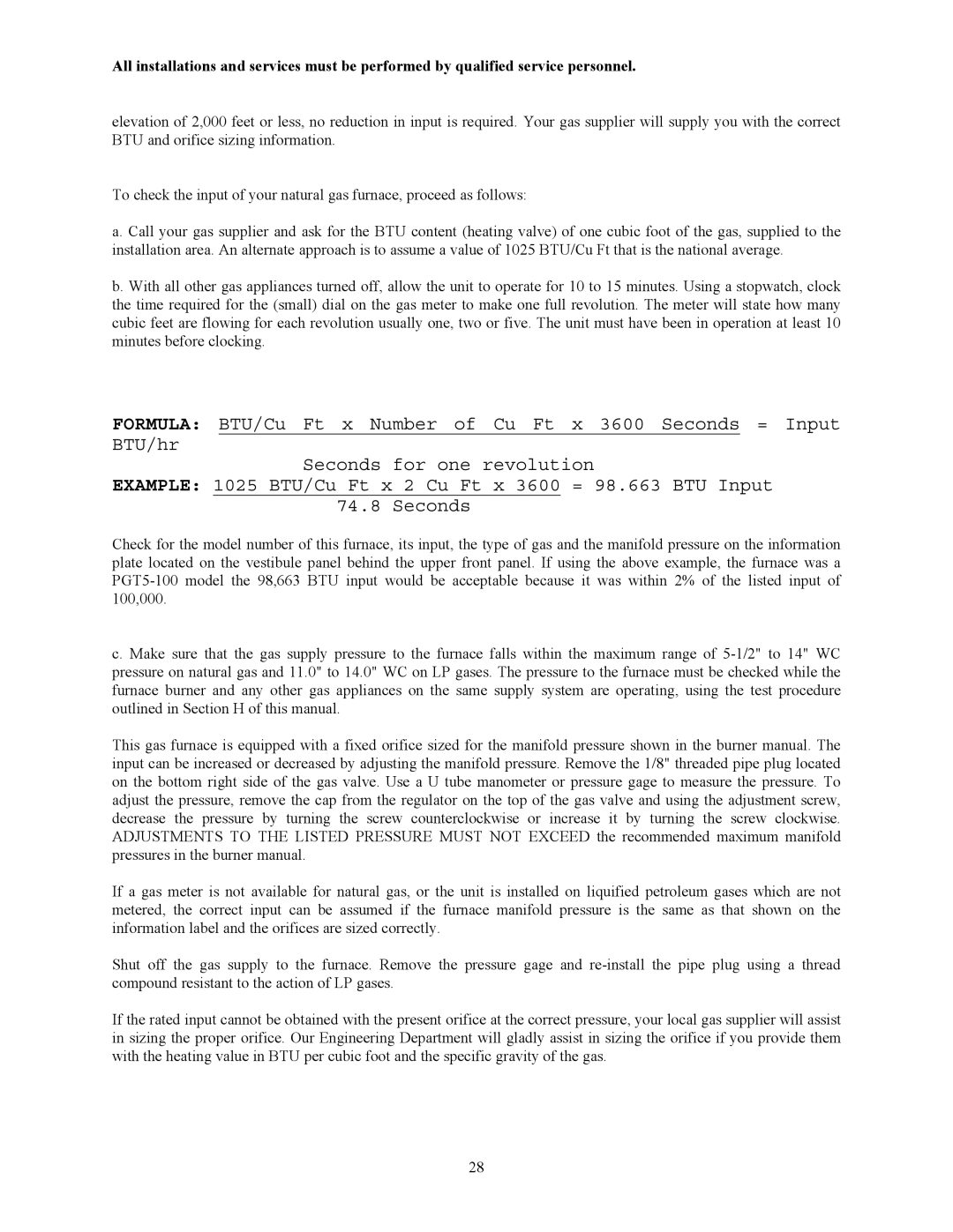
FORMULA: BTU/Cu Ft x Number of Cu Ft x 3600 Seconds = Input BTU/hr

Seconds for one revolution

EXAMPLE: 1025 BTU/Cu Ft x 2 Cu Ft x 3600 = 98.663 BTU Input 74.8 Seconds

Check for the model number of this furnace, its input, the type of gas and the manifold pressure on the information plate located on the vestibule panel behind the upper front panel. If using the above example, the furnace was a PGT5-100 model the 98,663 BTU input would be acceptable because it was within 2% of the listed input of 100,000.

c. Make sure that the gas supply pressure to the furnace falls within the maximum range of 5-1/2" to 14" WC pressure on natural gas and 11.0" to 14.0" WC on LP gases. The pressure to the furnace must be checked while the furnace burner and any other gas appliances on the same supply system are operating, using the test procedure outlined in Section H of this manual.

This gas furnace is equipped with a fixed orifice sized for the manifold pressure shown in the burner manual. The input can be increased or decreased by adjusting the manifold pressure. Remove the 1/8" threaded pipe plug located on the bottom right side of the gas valve. Use a U tube manometer or pressure gage to measure the pressure. To adjust the pressure, remove the cap from the regulator on the top of the gas valve and using the adjustment screw, decrease the pressure by turning the screw counterclockwise or increase it by turning the screw clockwise. ADJUSTMENTS TO THE LISTED PRESSURE MUST NOT EXCEED the recommended maximum manifold pressures in the burner manual.

If a gas meter is not available for natural gas, or the unit is installed on liquified petroleum gases which are not metered, the correct input can be assumed if the furnace manifold pressure is the same as that shown on the information label and the orifices are sized correctly.

Shut off the gas supply to the furnace. Remove the pressure gage and re-install the pipe plug using a thread compound resistant to the action of LP gases.

If the rated input cannot be obtained with the present orifice at the correct pressure, your local gas supplier will assist in sizing the proper orifice. Our Engineering Department will gladly assist in sizing the orifice if you provide them with the heating value in BTU per cubic foot and the specific gravity of the gas.

28

Page 30
Image 30
Thermo Products PGL20-180, PGT16-160, PGT5-100, PGT11-125, PGL37-312, PGL39-400, PGL33-250 service manual

PGL33-250, PGL39-400, PGL37-312, PGT11-125, PGL20-180 specifications

Thermo Products offers a robust lineup of heating devices designed to meet diverse industrial requirements. Among these, models PGL33-250, PGT5-100, PGL39-400, PGL20-180, and PGT11-125 stand out for their innovative technology and exceptional performance.

The PGL33-250 is particularly noted for its high output, making it an ideal choice for larger industrial applications. With an advanced heating element, it ensures rapid temperature increases while maintaining consistent heat distribution. This model is equipped with smart control systems that allow for remote monitoring and adjustments, enhancing operational efficiency.

Next in the lineup is the PGT5-100, a compact yet powerful solution perfectly suited for smaller spaces where efficiency is key. It features an energy-efficient design that reduces operational costs without compromising on performance. The PGT5-100 includes built-in overheat protection, ensuring safe operation even in demanding environments.

The PGL39-400 takes versatility to the next level. Its dual-mode heating capabilities allow users to switch between high-efficiency and high-output settings, catering to varying workload requirements. The advanced insulation technology employed in this model minimizes heat loss, thereby maximizing energy efficiency and reducing environmental impact.

In the mid-range category, the PGL20-180 offers robust performance with a focus on user-friendly features. This model includes a sophisticated digital control panel, providing real-time temperature readings and programmable settings. Its lightweight design makes installation straightforward, while its durability ensures long-term reliability.

Finally, the PGT11-125 stands out for its innovative thermal regulation system. This system adapts the heating output based on real-time environmental conditions, ensuring optimal performance at all times. The PGT11-125 is also constructed using high-quality materials that resist corrosion and wear, making it suitable for various industrial applications.

Collectively, these models from Thermo Products exemplify the company's commitment to quality and technological advancement. With features such as smart controls, advanced insulation, and dual-mode operation, these heating solutions not only offer efficient performance but also contribute to energy savings and a reduced carbon footprint. As industries continue to evolve, Thermo Products remains at the forefront, providing reliable and innovative heating solutions for all industrial needs.