Manuals
/
Thermo Products
/
Household Appliance
/
Burner
Thermo Products
PGL33-250, PGT16-160, PGT5-100, PGL20-180, PGT11-125 Vii. Replacement Parts
Models:
PGL33-250
PGL39-400
PGL37-312
PGT11-125
PGL20-180
PGT5-100
PGT16-160
1
34
38
38
Download
38 pages
37.07 Kb
31
32
33
34
35
36
37
38
<
>
Troubleshooting
Install
Orifice Chart
Vii. Replacement Parts
Maintenance
O. Wiring
MIDCO RE32 BURNER ADJUSTMENT
1.1X TR TEMPERATURE RISE = HEATING CFM EXAMPLES
Page 34
Image 34
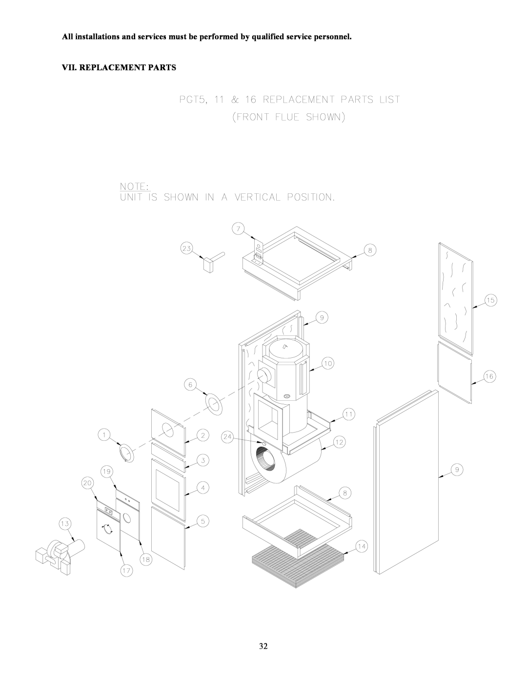
All installations and services must be performed by qualified service personnel.
VII. REPLACEMENT PARTS
32
Page 33
Page 35
Page 34
Image 34
Page 33
Page 35
Contents
PGL20-180, PGL33-250, PGL37-312,& PGL39-400
MODELS PGT5-100, PGT11-125, PGT16-160
MG-807C
TABLE OF CONTENTS
SECTION
Page
CAUTION When installing the burner, it should be noted that the loose fill insulation and fiber chambers are made with ceramic fibers. Currently, there are no known chronic health effects in humans associated with long term exposure to ceramic fibers. The International Agency for Research on Cancer IARC based on its review of studies that injected ceramic fiber into the abdomens of hamsters and rats have classified fibrous glass wool, mineral wool both rock wool and slag wool and ceramic fiber as group 2B carcinogens. A group 2B agent is considered by IARC to have the possibility of being carcinogenic to humans. IARC has also classified these fibrous materials as group 2A carcinogens when they have undergone long term exposure to temperatures greater than 18000F. A group 2A agent is considered to have the probability of being carcinogenic to humans. For these reasons, we suggest the use of a 3M 9900, 3M 8710 or equivalent mask when working with any ceramic fiber products. For further information, contact the Manager of Customer Service for Rex Roto Corporation at
A. CODES AND CLEARANCES
II. GENERAL INSTALLATION
I. GENERAL INSTRUCTIONS
B. CONSTRUCTION MATERIALS a. COMBUSTIBLE MATERIAL
MODEL NO
MAKE-UPAIR
D. VENTING
Page
E. VENT DAMPERS
F. CONDENSING IN THE CHIMNEY
H. GENERAL GAS PIPING
I. INSTALLATION OF NATURAL GAS PIPING
BLACK PIPE SIZE FOR NATURAL GAS
TYPICAL PIPING FOR TWO STAGE REGULATION
COPPER TUBING SIZE FOR LIQUIFIED PETROLEUM GASES
K. BURNER INSTALLATION
TOP VIEW BURNER INSERTION ILLUSTRATION PGL
TWO PIECE MOUNTING PLATE
SIDE VIEW BURNER INSERTION ILLUSTRATION PGT
MIDCO RE32 BURNER ADJUSTMENT
HORIZONTAL FURNACE POSITIONS
Manifold Gas Pressure
Furnace Model
Orifice Size
No. Turns Closed
L. REQUIREMENTS AND SIZING OF DUCT WORK
EXAMPLE Heating output of furnace is 100,000 x 1.4 ÷ 100 = 1400 CFM. Air conditioning installed is 4 tons
1. HEATING CFM BTUS OUTPUT OF FURNACE
1.1X TR TEMPERATURE RISE = HEATING CFM EXAMPLES
DUCT WORK/AIR CONDITIONING
A.110,000 BTU OUTPUT
M. FILTERS
A. PGT HORIZONTAL UNITS B. PGL LOWBOY
WITHOUT AIR CONDITIONING
N. FAN AND LIMIT POSITION AND LOCATION
LOCATION FOR LOWBOYS & HORIZONTALS
FAN & LIMIT LOCATION FOR HORIZONTALS
O. WIRING
LATEST EDITION
Page
Page
Page
Page
Wiring
OPERATING INSTRUCTIONS
C. ADJUSTMENT OF BTU INPUT RATE
II.STARTING THE UNIT A. INITIAL START UP
B. BURNER COMBUSTION
Seconds for one revolution
IV. INSTALLERS INSTRUCTIONS TO USER
ORIFICE CHART
D. FURNACE CHECKOUT PROCEDURE
FURNACE
V. DEALER MAINTENANCE A. ELECTRICAL
B. CLEANING HEAT EXCHANGER
VI. TROUBLESHOOTING
VII. REPLACEMENT PARTS
Page
Page