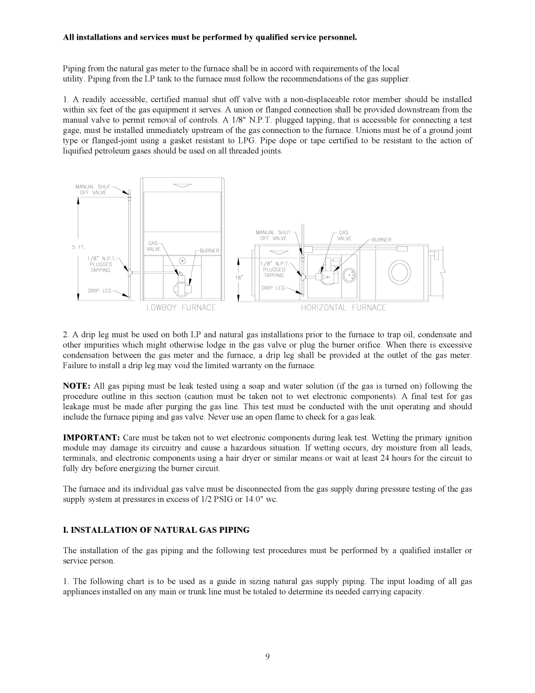
PGL33-250, PGL39-400, PGL37-312, PGT11-125, PGL20-180 specifications
Thermo Products offers a robust lineup of heating devices designed to meet diverse industrial requirements. Among these, models PGL33-250, PGT5-100, PGL39-400, PGL20-180, and PGT11-125 stand out for their innovative technology and exceptional performance.The PGL33-250 is particularly noted for its high output, making it an ideal choice for larger industrial applications. With an advanced heating element, it ensures rapid temperature increases while maintaining consistent heat distribution. This model is equipped with smart control systems that allow for remote monitoring and adjustments, enhancing operational efficiency.
Next in the lineup is the PGT5-100, a compact yet powerful solution perfectly suited for smaller spaces where efficiency is key. It features an energy-efficient design that reduces operational costs without compromising on performance. The PGT5-100 includes built-in overheat protection, ensuring safe operation even in demanding environments.
The PGL39-400 takes versatility to the next level. Its dual-mode heating capabilities allow users to switch between high-efficiency and high-output settings, catering to varying workload requirements. The advanced insulation technology employed in this model minimizes heat loss, thereby maximizing energy efficiency and reducing environmental impact.
In the mid-range category, the PGL20-180 offers robust performance with a focus on user-friendly features. This model includes a sophisticated digital control panel, providing real-time temperature readings and programmable settings. Its lightweight design makes installation straightforward, while its durability ensures long-term reliability.
Finally, the PGT11-125 stands out for its innovative thermal regulation system. This system adapts the heating output based on real-time environmental conditions, ensuring optimal performance at all times. The PGT11-125 is also constructed using high-quality materials that resist corrosion and wear, making it suitable for various industrial applications.
Collectively, these models from Thermo Products exemplify the company's commitment to quality and technological advancement. With features such as smart controls, advanced insulation, and dual-mode operation, these heating solutions not only offer efficient performance but also contribute to energy savings and a reduced carbon footprint. As industries continue to evolve, Thermo Products remains at the forefront, providing reliable and innovative heating solutions for all industrial needs.

