4. NOMENCLATURE AND FUNCTIONS
[Front]
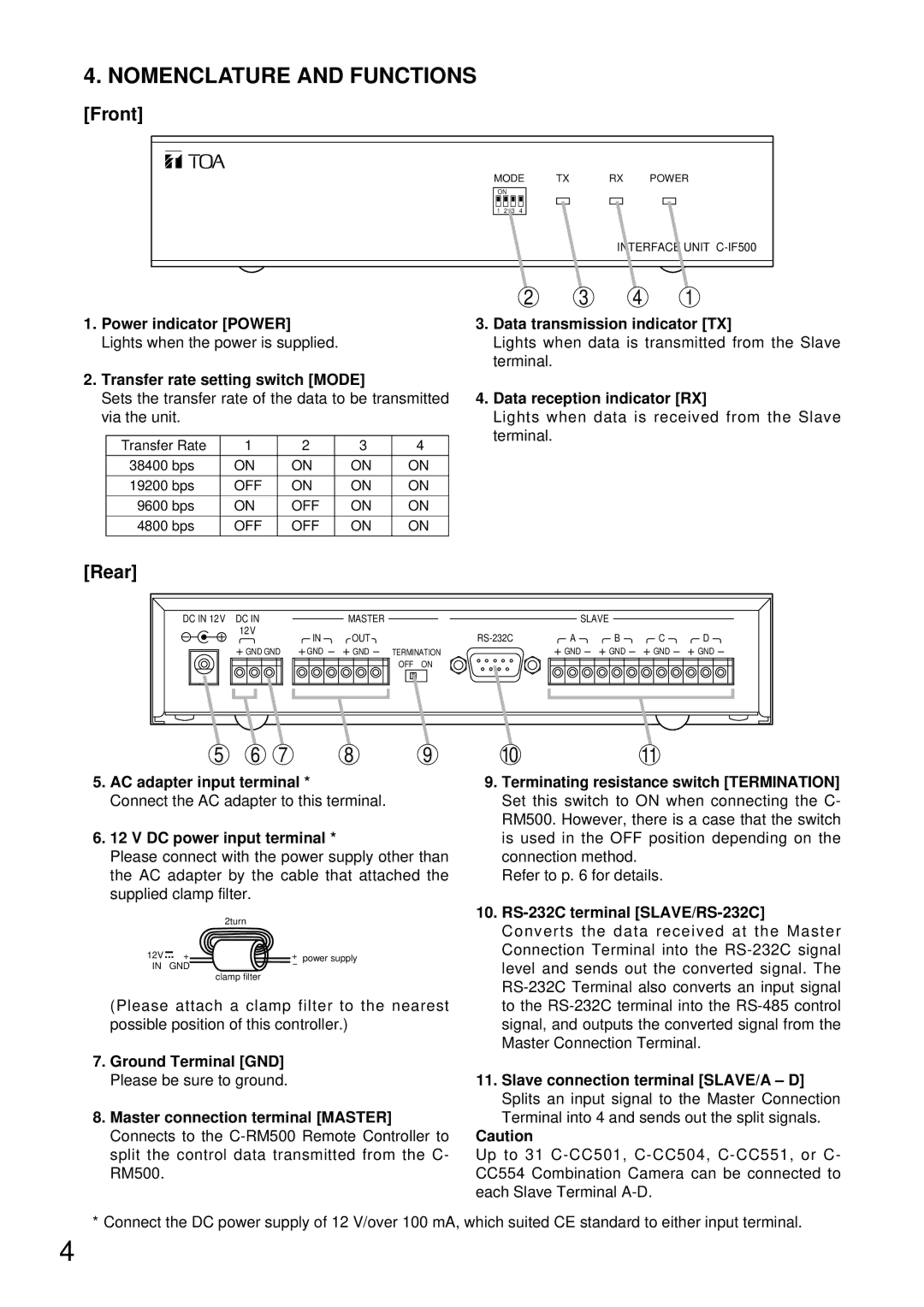
MODE TX RX POWER
ON
1 2 3 4
INTERFACE UNIT
1.Power indicator [POWER] Lights when the power is supplied.
2.Transfer rate setting switch [MODE]
Sets the transfer rate of the data to be transmitted via the unit.
Transfer Rate | 1 | 2 | 3 | 4 |
38400 bps | ON | ON | ON | ON |
|
|
|
|
|
19200 bps | OFF | ON | ON | ON |
|
|
|
|
|
9600 bps | ON | OFF | ON | ON |
4800 bps | OFF | OFF | ON | ON |
2 3 4 1
3.Data transmission indicator [TX]
Lights when data is transmitted from the Slave terminal.
4.Data reception indicator [RX]
Lights when data is received from the Slave terminal.
[Rear]
DC IN 12V | DC IN |
|
| MASTER |
|
|
| SLAVE |
|
|
|
| 12V |
| IN | OUT |
|
| A | B | C | D | |
|
|
|
|
| |||||||
| GND GND | GND | GND | TERMINATION |
| GND | GND | GND | GND | ||
|
|
|
|
| OFF | ON |
|
|
|
|
|
5 | 6 | 7 |
| 8 |
| 9 | 10 |
|
| 11 |
|
5.AC adapter input terminal *
Connect the AC adapter to this terminal.
6.12 V DC power input terminal *
Please connect with the power supply other than the AC adapter by the cable that attached the supplied clamp filter.
|
| 2turn |
|
12V | + | + | power supply |
IN | GND | - |
|
|
| clamp filter |
|
(Please attach a clamp filter to the nearest possible position of this controller.)
7.Ground Terminal [GND] Please be sure to ground.
8.Master connection terminal [MASTER] Connects to the
9.Terminating resistance switch [TERMINATION] Set this switch to ON when connecting the C- RM500. However, there is a case that the switch is used in the OFF position depending on the connection method.
Refer to p. 6 for details.
10.
11.Slave connection terminal [SLAVE/A – D] Splits an input signal to the Master Connection Terminal into 4 and sends out the split signals.
Caution
Up to 31
* Connect the DC power supply of 12 V/over 100 mA, which suited CE standard to either input terminal.
4