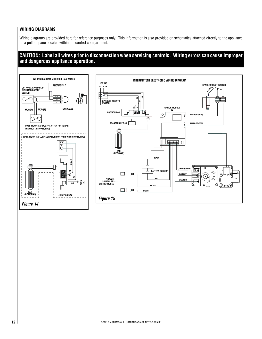
Wiring Diagrams
Wiring diagrams are provided here for reference purposes only. This information is also provided on schematics attached directly to the appliance on a pullout panel located within the control compartment.
CAUTION: Label all wires prior to disconnection when servicing controls. Wiring errors can cause improper and dangerous appliance operation.
| WIRING DIAGRAM MILLIVOLT GAS VALVES |
| ||
OPTIONAL APPLIANCE- | THERMOPILE |
|
| |
|
|
| ||
MOUNTED ON/OFF |
|
|
| |
SWITCH |
|
|
|
|
|
|
|
| |
|
| TP |
|
|
|
| TH |
|
|
BK/W(1) | BK/W(1) | GAS VALVE |
| |
|
| |||
THERMOSTAT (OPTIONAL) |
|
|
| |
WALL MOUNTED CONFIGURATION FOR FAN SWITCH (OPTIONAL) | ||||
|
| BLACK |
|
|
|
| BK |
|
|
|
| R | W |
|
|
| GR | 120 V AC | |
FAN |
|
|
|
|
(OPTIONAL) | JUNCTION BOX |
|
| |
|
|
|
| |
Figure 14 |
|
|
| |
INTERMITTENT ELECTRONIC WIRING DIAGRAM |
|
|
| |||
120 VAC |
|
| SPARK TO PILOT IGNITOR |
| ||
BK W GR |
|
|
| |||
|
|
|
|
|
| |
| BK | GR |
|
|
|
|
OPTIONAL BLOWER |
| W |
|
|
|
|
SWITCH |
|
|
|
|
|
|
BK | R |
| IGNITOR MODULE |
|
|
|
JUNCTION BOX |
|
| 3V |
|
|
|
|
| BLACK (IGNITOR) |
|
|
| |
|
|
|
|
|
| |
TRANSFORMER 3V |
|
| BLACK (SENSOR) |
|
|
|
FAN |
|
|
|
|
|
|
(OPTIONAL) |
|
|
|
|
|
|
|
| BLACK |
|
|
|
|
|
|
| ORANGE (THTP) |
|
|
|
|
| BATTERY |
| IN |
| |
|
|
| BLACK (TP) |
|
|
|
|
|
| LO | HI |
| PILOT |
TO WALL |
| RED | GREEN (TH) |
| OUT | IN |
|
|
| ||||
SWITCH, FRS |
|
|
|
| VENT |
|
OR THERMOSTAT |
|
|
|
|
| |
| BROWN |
|
|
|
| |
|
|
|
|
|
| |
|
| BROWN |
|
|
|
|
Figure 15 |
|
|
|
|
|
|
12
NOTE: DIAGRAMS & ILLUSTRATIONS ARE NOT TO SCALE.