Burner Adjustments
(QUALIFIED TECHNICIANS ONLY)
Flame Appearance and sooting
Proper flame appearance is a flame which is blue at the base and becomes
15minutes of operation. If after a short period the flame stays lowered blue, or if the flame is orange with evidence of sooting (black tip), the air shutter opening may need to be adjusted.
If the air shutter openings closed too far, sooting may develop. Sooting is indicated by black puffs developing at the tips of very long orange flames. Sooting results in black deposits forming on the logs, appliance inside surfaces and on exterior surfaces adjacent to the vent termination. Soot- ing is caused by incomplete combustion in the flames and lack of combustion air entering the air shutter opening. To achieve a warm yellow-
Air Shutter Adjustment Guidelines
• If there is smoke or soot present, first check |
the log set positioning to ensure that the |
flames are not impinging on any of the logs. |
If the log set is properly positioned and a |
sooting condition still exists, then the air |
shutter opening should be increased. |
• The more offsets in the vent system, the larger |
the air shutter opening will need to be. |
• An appliance operated with the air shutter |
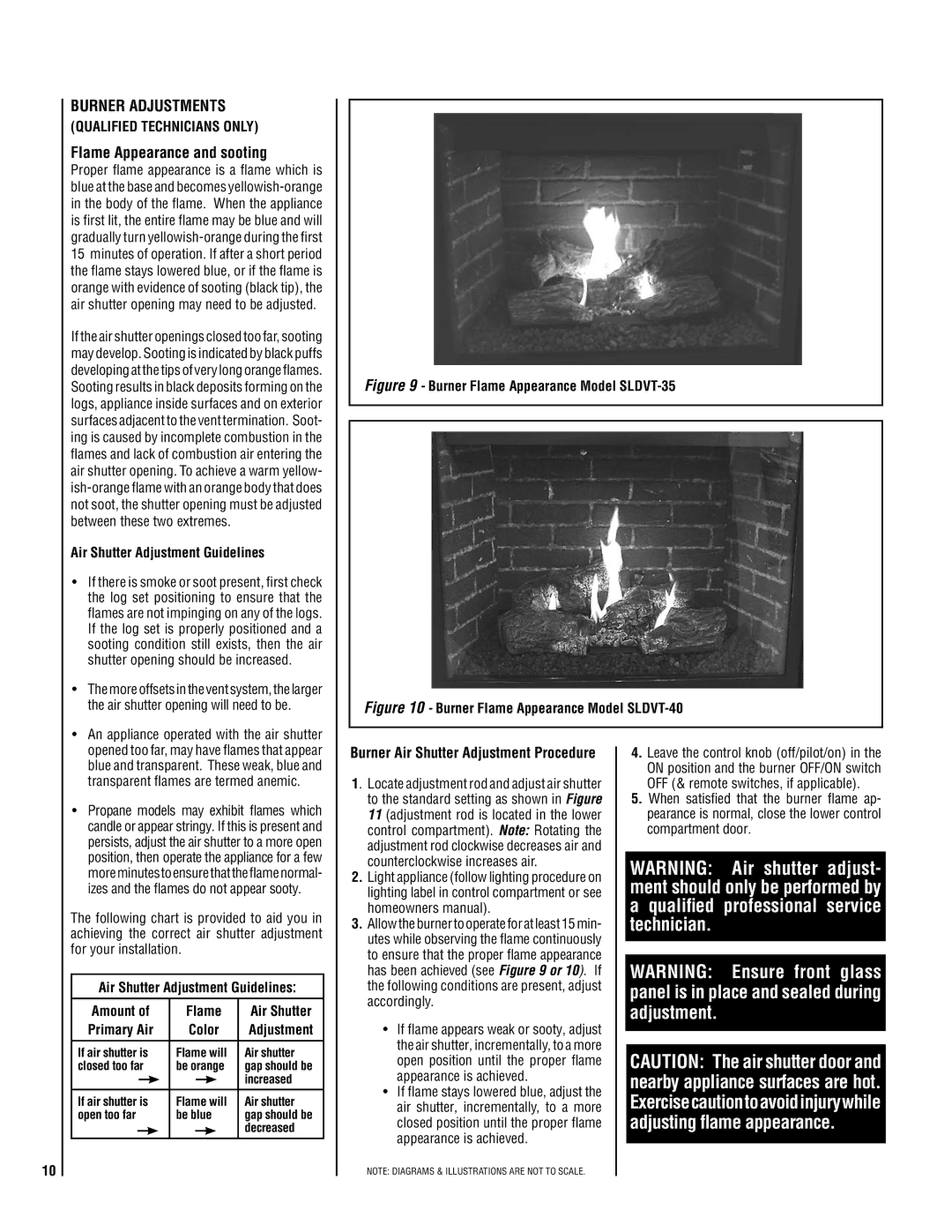
Figure 9 - Burner Flame Appearance Model SLDVT-35
Figure 10 - Burner Flame Appearance Model SLDVT-40
opened too far, may have flames that appear |
blue and transparent. These weak, blue and |
transparent flames are termed anemic. |
• Propane models may exhibit flames which |
candle or appear stringy. If this is present and |
persists, adjust the air shutter to a more open |
position, then operate the appliance for a few |
moreminutestoensurethattheflamenormal- |
izes and the flames do not appear sooty. |
The following chart is provided to aid you in achieving the correct air shutter adjustment for your installation.
Air Shutter Adjustment Guidelines:
Amount of | Flame | Air Shutter | ||||
Primary Air | Color | Adjustment | ||||
If air shutter is | Flame will | Air shutter | ||||
closed too far | be orange | gap should be | ||||
|
|
|
|
|
| increased |
|
|
|
|
|
| |
If air shutter is | Flame will | Air shutter | ||||
open too far | be blue | gap should be | ||||
|
|
|
|
|
| decreased |
|
|
|
|
|
| |
Burner Air Shutter Adjustment Procedure
1. Locate adjustment rod and adjust air shutter to the standard setting as shown in Figure 11 (adjustment rod is located in the lower control compartment). Note: Rotating the adjustment rod clockwise decreases air and counterclockwise increases air.
2.Light appliance (follow lighting procedure on lighting label in control compartment or see homeowners manual).
3.Allow the burner to operate for at least 15 min- utes while observing the flame continuously to ensure that the proper flame appearance has been achieved (see Figure 9 or 10). If the following conditions are present, adjust accordingly.
•If flame appears weak or sooty, adjust the air shutter, incrementally, to a more open position until the proper flame appearance is achieved.
•If flame stays lowered blue, adjust the air shutter, incrementally, to a more closed position until the proper flame appearance is achieved.
4.Leave the control knob (off/pilot/on) in the ON position and the burner OFF/ON switch OFF (& remote switches, if applicable).
5.When satisfied that the burner flame ap- pearance is normal, close the lower control compartment door.
WARNING: Air shutter adjust- ment should only be performed by a qualified professional service technician.
WARNING: Ensure front glass panel is in place and sealed during adjustment.
CAUTION: The air shutter door and nearby appliance surfaces are hot. Exercisecautiontoavoidinjurywhile adjusting flame appearance.
10
NOTE: DIAGRAMS & ILLUSTRATIONS ARE NOT TO SCALE.