10
In normal operation, at full rate, after 15 min- utes the following flame appearance should be observed:
Rear Burner Flame Characteristics – The rear flames should be yellow. The flames should extend about 3 – 4" above the center log (front of the unitized log group) for natu- ral gas and 2 – 3" above for propane (L.P.G.) gas (Figure 20 ).
Figure 20
Main Burner – The flames at the front burner holes will be blue becoming yellowish as they hit the
Appliance Operation
WARNING: THE LOWER CONTROL COM- PARTMENT AREA AND LOWER CONTROL COMPARTMENT ACCESS DOOR ARE EX- TREMELY HOT WHEN THE APPLIANCE IS INOPERATION. EXERCISEEXTREMECARE WHEN ACCESSING THIS AREA. TOUCH ONLY THE FAR ENDS OF THE LOWER CONTROL COMPARTMENT DOOR WHEN OPENING WHILE THE APPLIANCE IS HOT.
Step 14. Checking the System – With gas line installed run initial system checkout before closing up the front of the unit. Follow the pilot lighting instructions on page 16.
Note: Instructions are also found on the pull out panel located on the bottom surface of the appliance.
When first lighting the appliance, it will take a few minutes for the line to purge itself of air. Once purging is complete, the pilot and burner will light and operate as indicated in the instruc- tion manual. Subsequent lightings of the appli- ance will not require such purging. Inspect the pilot flame (remove logs, if necessary, handling carefully).
The pilot flame should be steady, not lifting or floating. Flame should be blue in color with traces of orange at the outer edge.
The top 3/8" (10 mm) at the pilot generator (thermopile) should be engulfed in the pilot flame (NG only).
Replace logs if removed for pilot inspection.
To light the burner; turn “ON” the optional remote wall switch (if installed) and rotate the gas valve control knob counterclockwise to the “ON” position.
Step 15. Installing the Optional Screen As- sembly – Retrieve the screen door frame. Po- sition the door frame in front of the firebox opening in the brackets at the base of the fireplace front opening. Lean the door frame back towards the fireplace ensuring that the frame seats evenly as it draws shut.
Installing the Optional Glass Door
Position the door frame in front of the firebox opening, with the joint in the gasket down. Locate the three (3) tabs at the bottom edge of the door frame into the three (3) brackets at the base of the fireplace front opening. Lean the door frame back towards the fireplace ensuring that the frame seats evenly as it draws shut.
Install the three (3)
Make sure the screws are tightened equally to avoid torquing the door (Figure 21 ).
Screws
Figure 21
NOTE: DIAGRAMS & ILLUSTRATION NOT TO SCALE.
OPTIONAL EQUIPMENT
An incomparable package of options are avail- able for use with these appliances. These op- tions can both customize the operation of these unique appliances and enhance their beauty and charming appeal. All options are available in kit form, are easy to install and are packaged complete with all required parts and instruc- tions. Some of the option kits need to be fitted prior to completing the installation of the appli- ance. The following paragraphs detail the kit options available for use with the appliances covered in this manual.
These outstanding optional items can be added individually or in sets of two or more to custom- ize your
The appliances covered in this manual are heater rated and produce a great deal of heat. Decorative brass trim pieces and hoods may tarnish because of their proximity to the heater opening and front face. Tarnishing of these pieces is normal, unavoidable and should be expected.
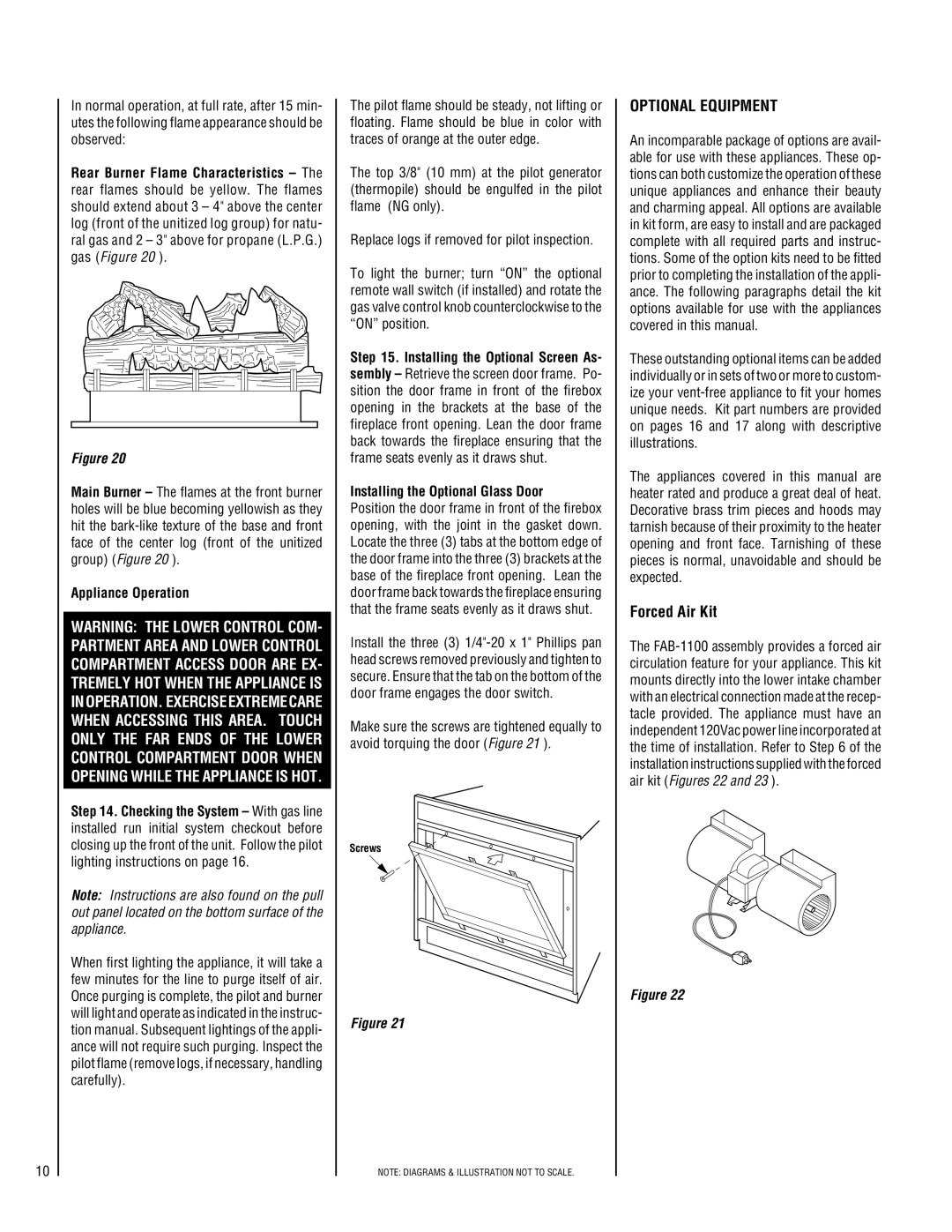
Forced Air Kit
The
Figure 22