Installation Procedure _____________________
CAUTION
Golf sprinklers are intended for installation at grade with full support of the body and piping system from the surrounding earth. Failure to provide full support may result in premature failure of the body and/or connecting fittings.
To assure maximum performance from your 734 Series Rotary Sprinklers, read these instructions completely prior to installation or service.
Swing Joints
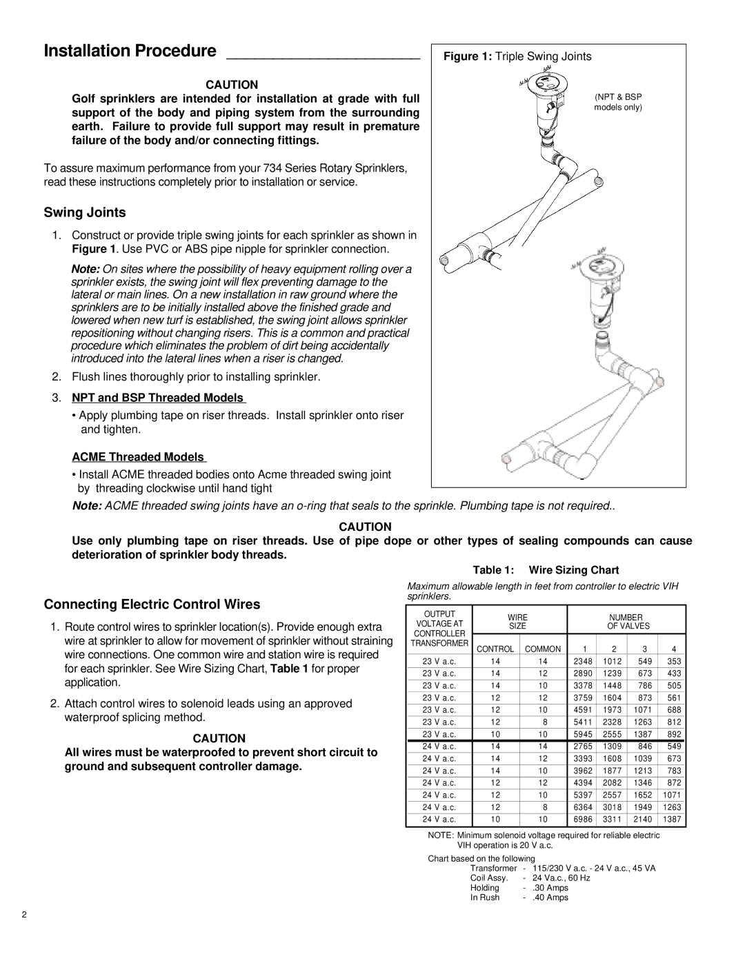
1.Construct or provide triple swing joints for each sprinkler as shown in Figure 1. Use PVC or ABS pipe nipple for sprinkler connection.
Note: On sites where the possibility of heavy equipment rolling over a sprinkler exists, the swing joint will flex preventing damage to the lateral or main lines. On a new installation in raw ground where the sprinklers are to be initially installed above the finished grade and lowered when new turf is established, the swing joint allows sprinkler repositioning without changing risers. This is a common and practical procedure which eliminates the problem of dirt being accidentally introduced into the lateral lines when a riser is changed.
2.Flush lines thoroughly prior to installing sprinkler.
3.NPT and BSP Threaded Models
•Apply plumbing tape on riser threads. Install sprinkler onto riser and tighten.
ACME Threaded Models
•Install ACME threaded bodies onto Acme threaded swing joint by threading clockwise until hand tight
Figure 1: Triple Swing Joints
(NPT & BSP models only)
(ACME
models only)
Note: ACME threaded swing joints have an
CAUTION
Use only plumbing tape on riser threads. Use of pipe dope or other types of sealing compounds can cause deterioration of sprinkler body threads.
Connecting Electric Control Wires
1.Route control wires to sprinkler location(s). Provide enough extra wire at sprinkler to allow for movement of sprinkler without straining wire connections. One common wire and station wire is required for each sprinkler. See Wire Sizing Chart, Table 1 for proper application.
2.Attach control wires to solenoid leads using an approved waterproof splicing method.
CAUTION
All wires must be waterproofed to prevent short circuit to ground and subsequent controller damage.
Table 1: Wire Sizing Chart
Maximum allowable length in feet from controller to electric VIH sprinklers.
|
|
|
|
|
|
|
|
|
|
|
|
|
|
|
|
| OUTPUT |
| WIRE |
|
|
| NUMBER |
|
| ||||
|
| VOLTAGE |
|
|
|
|
|
| ||||||
|
| VOLTAGE AT |
| SIZE |
|
|
| OF VALVES |
|
| ||||
|
|
| AT |
|
|
|
|
|
|
|
|
|
|
|
|
| CONTROLLER |
|
|
|
|
|
|
|
|
|
|
| |
|
| TRACONTRSFOLLERRMER |
| CONTROL | COMMON |
| 1 | 2 | 3 |
| 4 |
| ||
|
|
|
|
|
|
|
| |||||||
| 23 | V a.c. |
| 14 |
| 14 |
| 2348 | 1012 | 549 |
| 353 |
| |
|
|
|
|
|
|
|
|
|
|
|
|
|
|
|
| 23 | V a.c. |
| 14 |
| 12 |
| 2890 | 1239 | 673 |
| 433 |
| |
|
|
|
|
|
|
|
|
|
|
|
|
|
|
|
| 23 | V a.c. |
| 14 |
| 10 |
| 3378 | 1448 | 786 |
| 505 |
| |
|
|
|
|
|
|
|
|
|
|
|
|
|
|
|
| 23 | V a.c. |
| 12 |
| 12 |
| 3759 | 1604 | 873 |
| 561 |
| |
|
|
|
|
|
|
|
|
|
|
|
|
|
|
|
| 23 | V a.c. |
| 12 |
| 10 |
| 4591 | 1973 | 1071 |
| 688 |
| |
|
|
|
|
|
|
|
|
|
|
|
|
|
|
|
| 23 | V a.c. |
| 12 |
| 8 |
| 5411 | 2328 | 1263 |
| 812 |
| |
|
|
|
|
|
|
|
|
|
|
|
|
|
|
|
| 23 | V a.c. |
| 10 |
| 10 |
| 5945 | 2555 | 1387 |
| 892 |
| |
| 24 | V a.c. |
| 14 |
| 14 |
| 2765 | 1309 | 846 |
| 549 |
| |
| 24 | V a.c. |
| 14 |
| 12 |
| 3393 | 1608 | 1039 |
| 673 |
| |
|
|
|
|
|
|
|
|
|
|
|
|
|
|
|
| 24 | V a.c. |
| 14 |
| 10 |
| 3962 | 1877 | 1213 |
| 783 |
| |
|
|
|
|
|
|
|
|
|
|
|
|
|
|
|
| 24 | V a.c. |
| 12 |
| 12 |
| 4394 | 2082 | 1346 |
| 872 |
| |
|
|
|
|
|
|
|
|
|
|
|
|
|
|
|
| 24 | V a.c. |
| 12 |
| 10 |
| 5397 | 2557 | 1652 |
| 1071 |
| |
|
|
|
|
|
|
|
|
|
|
|
|
|
|
|
| 24 | V a.c. |
| 12 |
| 8 |
| 6364 | 3018 | 1949 |
| 1263 |
| |
|
|
|
|
|
|
|
|
|
|
|
|
|
|
|
| 24 | V a.c. |
| 10 |
| 10 |
| 6986 | 3311 | 2140 |
| 1387 |
| |
|
|
|
|
|
|
|
|
|
|
| ||||
|
| NOTE: Minimum solenoid voltage required for reliable electric |
|
| ||||||||||
|
|
| VIH operation is 20 V a.c. |
|
|
|
|
|
| |||||
|
| Chart based on the following |
|
|
|
|
|
| ||||||
|
|
|
| Transformer | - | 115/230 V a.c. - 24 V a.c., 45 VA |
|
| ||||||
|
|
|
| Coil Assy. | - | 24 Va.c., 60 Hz |
|
|
|
|
| |||
|
|
|
| Holding | - | .30 Amps |
|
|
|
|
|
| ||
|
|
|
| In Rush | - | .40 Amps |
|
|
|
|
|
| ||
2