FIELD REPLACEABLE UNIT DOCUMENTATION
TM
Satellite
1800 Series
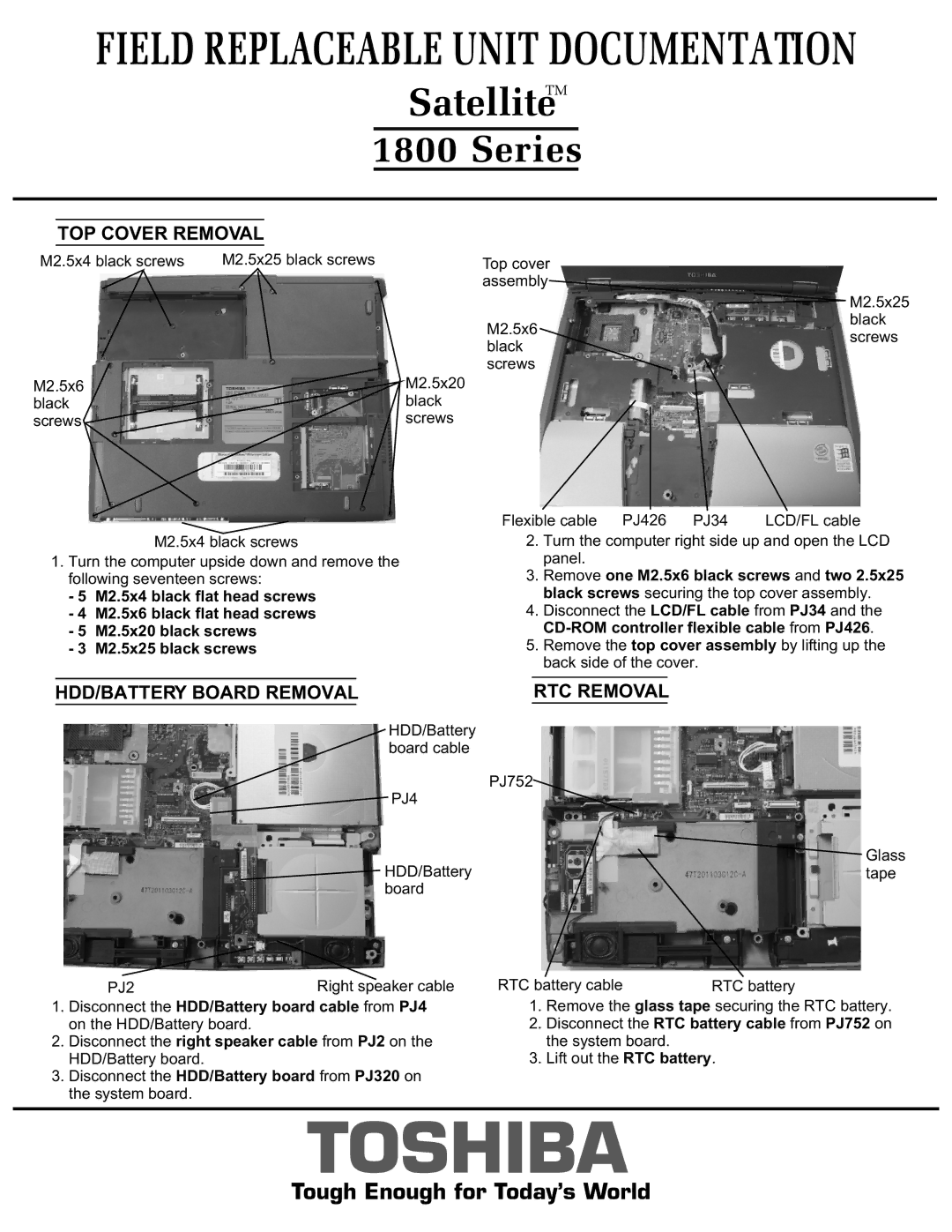
TOP COVER REMOVAL
M2.5x4 black screws | M2.5x25 black screws | Top cover |
|
| assembly |
![]() M2.5x25
M2.5x25
M2.5x6 black screws
M2.5x6 | M2.5x20 |
black | black |
screws | screws |
black screws
|
|
|
| Flexible cable PJ426 PJ34 | LCD/FL cable | |||
|
| M2.5x4 black screws | 2. | Turn the computer right side up and open the LCD | ||||
1. Turn the computer upside down and remove the |
|
| panel. |
| ||||
| following seventeen screws: | 3. | Remove one M2.5x6 black screws and two 2.5x25 | |||||
- 5 | M2.5x4 black flat head screws |
|
| black screws securing the top cover assembly. | ||||
- 4 | M2.5x6 black flat head screws | 4. | Disconnect the LCD/FL cable from PJ34 and the | |||||
- 5 | M2.5x20 black screws |
|
| |||||
- 3 | M2.5x25 black screws | 5. | Remove the top cover assembly by lifting up the | |||||
|
|
|
|
|
| back side of the cover. |
| |
|
|
|
|
|
|
|
|
|
| HDD/BATTERY BOARD REMOVAL |
| RTC REMOVAL |
| ||||
|
|
|
|
|
|
|
|
|
HDD/Battery |
|
board cable |
|
PJ4 | PJ752 |
| |
HDD/Battery | Glass |
tape | |
board |
|
| PJ2 | Right speaker cable | RTC battery cable | RTC battery | |
1. | Disconnect the HDD/Battery board cable from PJ4 | 1. | Remove the glass tape securing the RTC battery. | ||
| on the HDD/Battery board. |
| 2. | Disconnect the RTC battery cable from PJ752 on | |
2. | Disconnect the right speaker cable from PJ2 on the |
| the system board. |
| |
| HDD/Battery board. |
| 3. | Lift out the RTC battery. | |
3.Disconnect the HDD/Battery board from PJ320 on the system board.
TOSHIBA
Tough Enough for Today’s World