RW2SU / D-RW2SC Basic
Make your contribution to the environment
Precautions
Laser Safety
Introduction
Important Safeguards
Moisture Condensation Warning
Installation Location
Supplied Accessory
Avoid the Hazards of Electrical Shock and Fire
Dolby Digital Recording
Maintenance
Table of contents
Others
Function Setup
Playback
Editing
Features
Play
Compatibility
DVD disc types
Using different disc types for different purposes
Disc Mark Specification Remarks
Choosing a disc
For playback only
10 EN
Standards
On DVD-R discs
On DVD-RW discs
Marks on DVD video discs
Yes
Yes No
12 EN
Discs and purposes
Index to parts and controls
14 EN
Front Panel
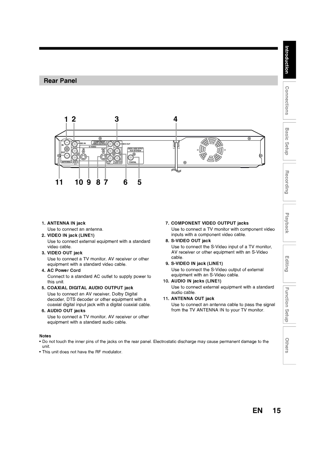
Rear Panel
Introduction Index to parts and controls cont’d
16 EN
Number buttons
Timer PROG. button
Setup button
OPEN/CLOSE a button
18 EN
Front Panel Display Guide
Display message
Open the cover Insert batteries
Installing batteries in the remote control
Using a remote control
Keep in mind the following when using the remote control
Display menu
Setup menu
On Screen menu
20 EN
Random Play
Disc Protect VR mode only
Format DVD-RW only
Finalize
Page
Connections
Connection to a TV
24 EN
Connections
To set progressive scan mode, refer to
Basic Audio
Video cable Commercially available Component Video cable
After you have completed the connections
Audio/Video cables
Cable TV Antenna Back of this unit Signal
RF modulator Connection
26 EN
With this setup
RF cable
Connect
Digital audio Coaxial input jack
Connection to an Audio System
28 EN
Method
Basic Setup
Press I/y ON/STANDBY
Initial setting
Basic Setup
30 EN
Press Enter to start Channel Preset
Using K / L, select Channel Press Enter
Channel setting
Setting channels automatically
Press Setup
Using K / L, select Auto Preset Press Enter
Press Setup after scanning
To select a channel
34 EN
Press Setup Using K / L, select Channel Press Enter
Using K / L, select Manual Preset Press Enter
Basic Setup Channel setting cont’d
Using K / L, select Add or Delete Press Enter
Press Setup to exit
Select the channel number to add or delete
Using K / L, select TV Audio Select Press Enter
Selecting TV stereo or SAP
36 EN
Using K / L, select Stereo or SAP Press Enter
Stereo
SAP Secondary Audio Program
Using K / L, select Auto Clock Setting Press Enter
Setting the clock
Auto Clock Setting
Press Setup Using K / L, select Clock. Press Enter
Setting will be activated
40 EN
Basic Setup Setting the clock cont’d
Press Enter again
Manual Clock Setting
Using K / L, enter the date month / day / year
Using K / L, enter the time hour / minute. Press / B
42 EN
Press K / L to select AM or PM Press Enter
Press Setup to exit, if Clock menu appears
Setting the Daylight Saving Time
Using K / L, select Daylight Saving Time
44 EN
Using K / L, select on or OFF Press Enter
Using K / L, select TV Aspect Press Enter
Selecting the TV aspect ratio
46 EN
Using K / L, select a desired format Press Enter
If you have a standard TV
If you have a widescreen TV
Page
Recording
Restrictions on recording
Information on DVD recording
50 EN
Information
Information on copy control
Making discs playable in other DVD players Finalize
After finalizing
52 EN
Using K / L, select Disc. Press Enter
Using K / L, select Format Press Enter
Selecting the Recording format
Using K / L, select Video mode or VR mode. Press Enter
Using K / L, select Format Mode Press Enter
54 EN
Reformatting a disc Setting for Auto Chapter
Recording Audio Select XP
Press Setup Using K / L, select Recording. Press Enter
Using K / L, select Recording Audio Select XP. Press Enter
Using K / L, select PCMor Dolby
Press OPEN/CLOSE a to close the disc tray
Basic recording
56 EN
Press OPEN/CLOSE a
Press REC I to start recording
Using REC MODE, select a recording mode
58 EN
Press Stop C to stop recording
Recording Basic recording cont’d
One-touch Timer Recording
Recording One-touch Timer Recording cont’d
60 EN
Press REC I repeatedly to select desired recording time
Timer Recording
Press Timer Prog
Using K / L, select a program number Press Enter
62 EN
Using K / L, enter the Date. Press B
Using K / L, enter the Start and End. Press B
Recording Timer Recording cont’d
Using K / L, select a recording mode
Using K / L, select the channel number to record. Press B
Press I/y ON/STANDBY to go into the timer standby mode
64 EN
If you have not set the clock yet
180 min 60 min 120 min 12cm Disc 240 min 360 min
Recording Mode
18 min 36 min 8cm Disc 72 min 108 min
144 min
Checking, canceling, or correcting
Timer programming
66 EN
Program set previously PROG. a has priority
Hints for Timer Recording
Priority of overlapped settings
When the recording time is partially overlapped
Settings for an external source
68 EN
Connection to an external source
Using K / L, select L2 Front or L1 Rear. Press Enter
Using K / L, select Select Video Press Enter
Before recording from an external source, see
Recording Settings for an external source cont’d
70 EN
Recording from an external source
SEP SLP EP
Select a recording mode pressing REC Mode
72 EN
Setting disc protection
Press Setup Using K / L, select Disc. Press Enter
Using K / L, select Disc Protect OFF
To cancel the disc protect
Using K / L, select Yes. Press Enter
Using K / L, select Finalize. Press Enter
Finalizing the discs
74 EN
Finalizing is completed
To cancel finalizing
Auto finalize
Press Setup Using K / L, select Recording. Press Enter
Using K / L, select Auto Finalize. Press
76 EN
Using K / L, select ON. Press Enter
Using K / L, select Disc Full or End Timer Rec. Press Enter
Page
Playback
Basic playback
80 EN
Playback
Press TOP Menu to display the title list
Press Stop C to stop playback
Using K / L/ / B, select a desired title Press Enter
Using K / L, select Play. Press Enter
82 EN
Playing back a DVD-VIDEO / Video CD / CD
Stop mode, press TOP Menu to call up the menu
When selecting track
84 EN
Playing MP3, WMA, Jpeg disc
Hints for MP3, WMA and Jpeg files
Pause
Playing discs using the Disc menu
Playing discs using the Title menu
86 EN
Press Return to go back to the title menu
Playing back a Video CD using the title menu
Cancelling and Recalling the PBC function
PBC function for Video CDs
Skipping TV commercials during play
88 EN
Resume Play
Rapid Play
During playback, press Pause F. Then press FWD D or REV E
Fast forward / Fast reverse
Slow forward / Slow reverse
During playback, press FWD D or REV E
90 EN
Zoom Marker Setup
Using / B, select . Press Enter
Special playback
Chapter
Using / B, select .Press Enter
Searching by Title, Chapter or Track
Searching by Time
92 EN
Repeat Play
Random Play
Slide Show
Using K / L, select Program Play. Press Enter
Using K / L, select a desired track. Press
Program Play
Display menu will appear
Switching subtitles Switching audio soundtrack
Using / B, select Press Enter
94 EN
Using K / L, select OFF, Type 1 or Type 2. Press Enter
Switching virtual surround system
Switching camera angles
96 EN
Reducing block noise
Using K / L, select Black Level. Press Enter
Adjusting Black Level
Page
Editing
Edit the recorded disc
Information on disc editing
100 EN
Guide to a title list
Type of title
Editing discs
Editing discs
102 EN
Deleting titles
Title will be deleted
Using K / L, select Title Delete Press Enter
Editing Editing discs cont’d
104 EN
Editing title names
Character
106 EN
Guide to edit title name on next
Press Return and then Return or Stop C to exit
Guide to edit title name
Select a desired character set using K/L, then Press Enter
Adding or deleting chapter marks
108 EN
Playlist Chapter Mark Add
Setting pictures for thumbnails
110 EN
Follow steps 1 to 3 on page 102 to display the Edit menu
Picture for thumbnail will be set
Deleting parts of titles
112 EN
Press Enter again to start the preview
114 EN
Using K / L, select Delete. Press Enter
Editing Function Setup Others
Dividing a title
116 EN
Playlist Title Dividing
Combining titles
118 EN
Using s / B, select Yes. Press Enter
Using K / L, select Add New Title Press Enter
120 EN
Adding titles to a Playlist
Using K / L / s / B, select a desired title Press Enter
Using K / L, select Delete Playlist Press Enter
122 EN
Erasing all Playlist
Final confirmation window will appear
OFF ON. Press Enter
Setting or releasing the title protection
124 EN
Confirm the indication
To protect the whole disc DVD-RW VR mode Only
To clear all the chapter marks, select OFF
Setting or clearing all the chapter marks in one title
Using K / L, select desired time period Press Enter
126 EN
Marks will be added or deleted
Page
Function Setup
130 EN
Tour of the Setup menu
Function Setup
Setup Items highlight is the default Contents
DTS
132 EN
Language setting
Press Setup Using K / L, select Playback Press Enter
Using K / L, select Language Press Enter
Subtitle Language Default OFF
Using K / L, select a desired item Press Enter
Disc Menu Language Default English
Audio Language Default Original
Function Setup Language setting cont’d
When you finish entering the code, press Enter
134 EN
Display setting
Press Setup Using K / L, select Display Press Enter
OSD Language Default English
Using K / L, select a setting. Press Enter
Function Setup Display setting cont’d Angle Icon Default on
Screen Saver Default 10 minutes
FL Dimmer Default Bright
Digital Out
Audio setting
Press Setup Using K / L, select Playback. Press Enter
Using K / L, select Audio. Press Enter
138 EN
Function Setup Audio setting cont’d
When playing disc with copyright protection
When playing a DVD-RW disc recorded in VR mode
Select a setting using K / L, then press Enter
Dynamic Range Control Default on
Settings for Parental lock level
Using K / L, select Parental Lock
140 EN
Ratings 1 to
Using K / L, select the desired level Press Enter
Parental Lock Default All
Using K / L, change the parental level. Press Enter All
142 EN
Function Setup Settings for Parental lock level cont’d
Using K / L, select Video. Press Enter
Settings for Progressive Scan Mode
144 EN
Using K / L, select Progressive Press Enter
Using / B, select Yes. Press Enter
Function Setup Settings for Progressive Scan Mode cont’d
Using K / L, select Yes. Press Enter within 15 seconds
Settings for Still Mode
Using K / L, select a setting. Press Enter
146 EN
Others
148 EN
Troubleshooting
Recording/Timer Recording/Editing
150 EN
Error message
Cprm
152 EN
Frequently Asked Questions
Language code
154 EN
Glossary
Sampling frequency
Playlist
Progressive Scan 525p/480p
Regions code
Tuner
Specifications
156 EN
General
Limited Warranty
158 EN
Others