Guide Specification –
5.3.5Overload Capacity:
The Inverter output shall be capable of providing an overload current of 125% for 2 min. and 150% for 1 min. A message on the control panel shall indicate this condition. If the time limit associated with the overload condition expires, or the overload is in excess of the set current limit, the load power shall transfer to the bypass source without interruption.
5.4Static Bypass Circuit:
5.4.1General:
An integral static bypass circuit shall be provided to supply an alternate source of power to the critical load in the event the inverter cannot supply rated output power. The bypass circuit shall be capable of supplying the UPS rated load current and accommodate fault clearing.
The 100% duty rated static bypass panel shall be composed of a thyristor switch with a
The UPS system logic shall employ sensing which shall cause the thyristor switch to energize and provide an uninterrupted transfer of the load to the bypass source when any of the following limitations are exceeded:
Inverter output undervoltage or overvoltage.
Overloads exceeding 125% for 2 min., or 150% for 1 min. DC circuit undervoltage or overvoltage.
Final discharge voltage of system battery is reached and the bypass source is present, available, and within tolerance range
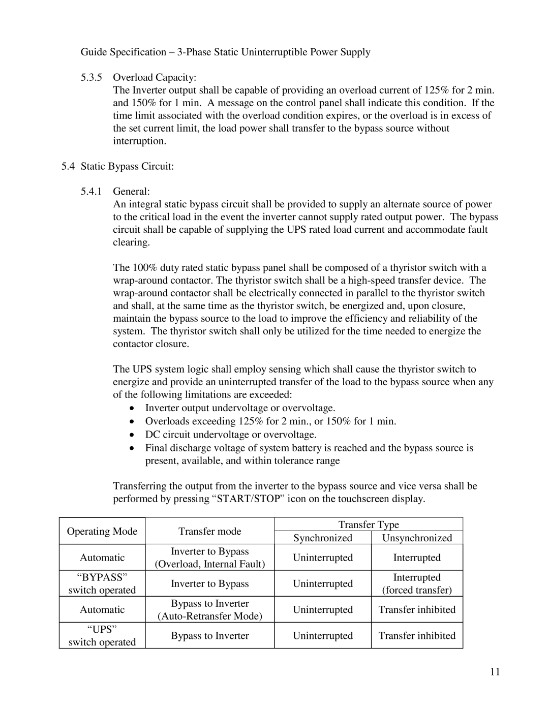
Transferring the output from the inverter to the bypass source and vice versa shall be performed by pressing “START/STOP” icon on the touchscreen display.
Operating Mode
Transfer mode
Transfer Type
Synchronized Unsynchronized
Automatic | Inverter to Bypass | Uninterrupted | Interrupted | |
(Overload, Internal Fault) | ||||
|
|
| ||
“BYPASS” | Inverter to Bypass | Uninterrupted | Interrupted | |
switch operated | (forced transfer) | |||
|
| |||
Automatic | Bypass to Inverter | Uninterrupted | Transfer inhibited | |
|
|
| ||
“UPS” | Bypass to Inverter | Uninterrupted | Transfer inhibited | |
switch operated | ||||
|
|
|
11