5. CONNECTIONS AND OPERATIONS
Notes on connecting
•Power plugs to connected equipment must be disconnected before installation.
•A
•For details of wiring and operation of equipment to be connected, refer to their operation manuals.
•Coaxial cables for video signals and the power cord are not supplied with the camera.
Refer to the operations manuals of connected equipment for detailed wiring and overall operation instructions.
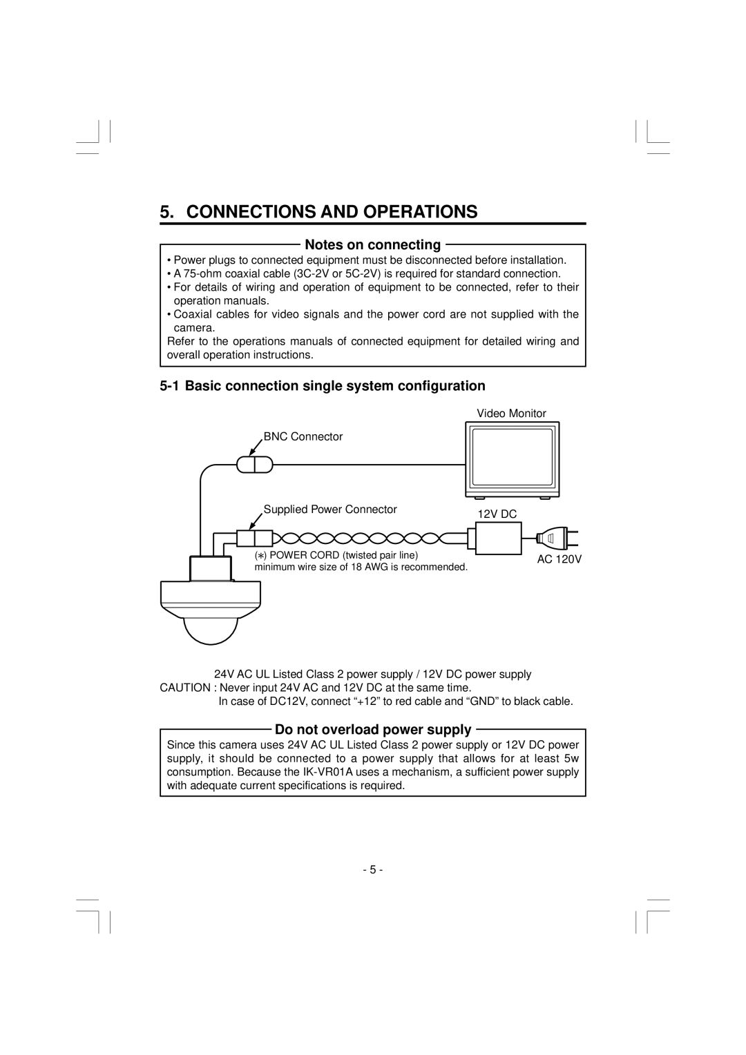
5-1 Basic connection single system configuration
Video Monitor
BNC Connector
Supplied Power Connector | 12V DC | |
| ||
( ) POWER CORD (twisted pair line) | AC 120V | |
minimum wire size of 18 AWG is recommended. | ||
|
24V AC UL Listed Class 2 power supply / 12V DC power supply CAUTION : Never input 24V AC and 12V DC at the same time.
In case of DC12V, connect “+12” to red cable and “GND” to black cable.
Do not overload power supply
Since this camera uses 24V AC UL Listed Class 2 power supply or 12V DC power supply, it should be connected to a power supply that allows for at least 5w consumption. Because the
- 5 -